Validation of our simulation models
Published on September 28, 2020
Here’s how we check that our simulation models match reality ! At imperix, we strongly believe that accurate simulation results help our customers develop efficient control algorithm, and eventually speed up the transition to real-world experiments. But how do we make sure that our models actually represent what happens on a real controller? I’m going […]
Here’s how we check that our simulation models match reality !
At imperix, we strongly believe that accurate simulation results help our customers develop efficient control algorithm, and eventually speed up the transition to real-world experiments. But how do we make sure that our models actually represent what happens on a real controller?
I’m going to briefly show you a particular example of how we have validated our carrier-based modulator models on Simulink.
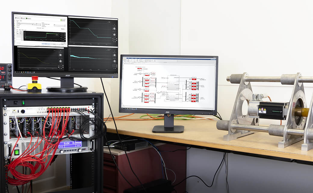
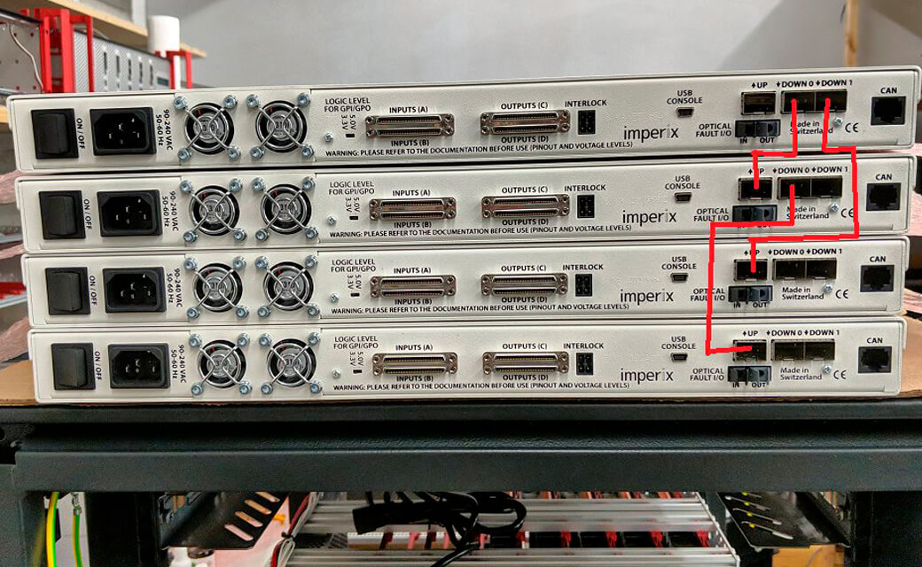
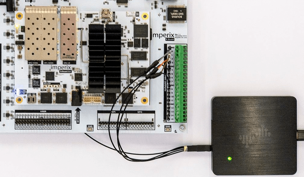
The process is quite simple and straightforward: we capture the PWM signals from a simulation run and compare them with those measured on a B-Board PRO that runs the exact same model. The real PWM signals are measured using a logic analyzer and the data is transferred to the PC to be analyzed.
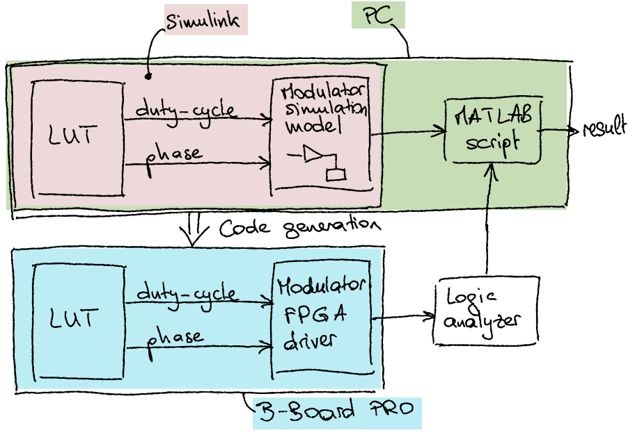
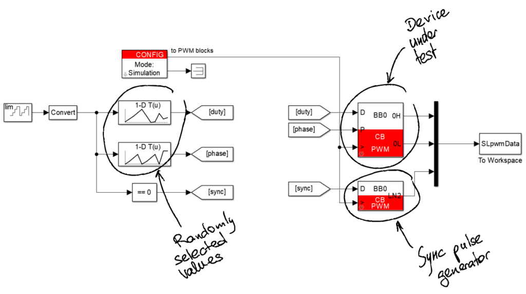
To make sure that the test is as generic as possible, we use randomly generated duty-cycle and phase values, stored in a lookup table.
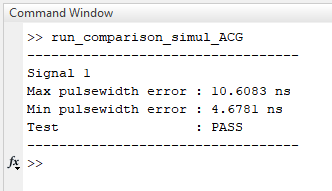
Finally, we run a MATLAB script that compares the PWM signals, using a synchronization pulse to align the simulation and experimental time axes.
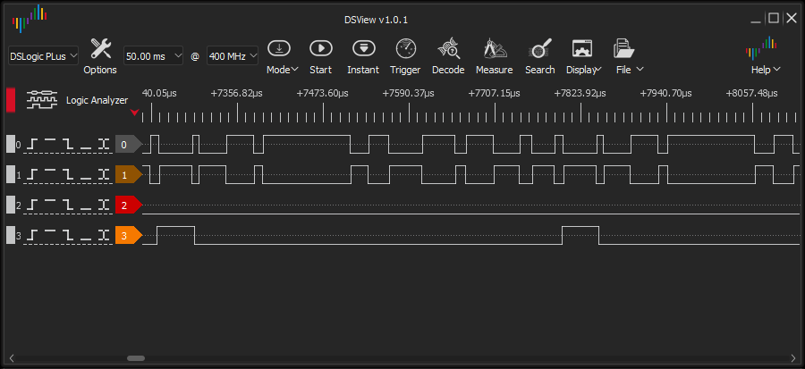
The tolerated error between simulation and experimental results takes into account the PWM resolution of the B-Board PRO (4 ns) and the time resolution of the logic analyzer (2.5 ns). In total, an error of 13 ns on a pulse width is tolerated. The test is then marked as “PASS” if none of the simulated PWM pulses differ from the measured pulses by more than 13 ns.