LOW LATENCY COMMUNICATION
THE KEY TO DISTRIBUTED CONTROL
RealSync network and protocol
The imperix proprietary RealSync communication protocol is tailored for ultra-fast data exchanges between digital control devices.
Our protocol is optimized for the transfer of small data packets, but with high interrupt rates. This guarantees the lowest achievable latency, which is essential to digital control systems in general.
This performance is essential to our networked control solutions, built using our fully programmable converter controllers.
Imperix RealSync technology in three points
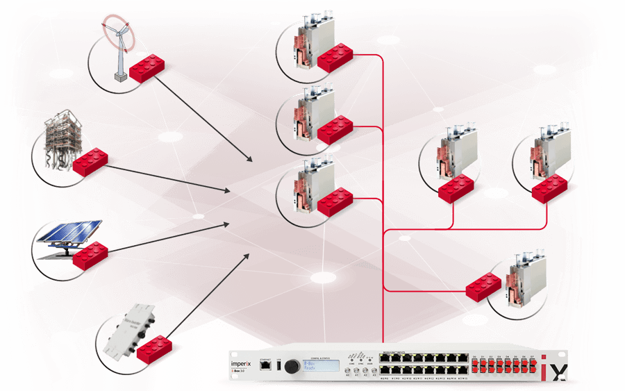
With imperix controllers, flexible and scalable control systems can be implemented by simply stacking hardware units, or arranging them in more complex configurations. In essence, our distributed converter control solutions rely on three pillars:
How much is low-latency?
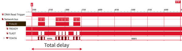
In discrete-time control systems, the total control delay (somewhat defining the maximum achievable control bandwidth) is a function of the sampling, interrupt, and PWM switching frequencies.
At imperix, we consider that communication latency only contributes marginally to the total delay when it represents a fraction of it.
In a typically multi-controllers configuration, data communication latency represents about 100-500ns (see more details below).
BENEFITS OF STANDARDIZED POWER ELECTRONIC BUILDING BLOCKS
The use of standardized building block is attracting a growing interest in power electronics. Indeed, this offers various economies of scale in the manufacturing of power converters. Besides, mechanical design and system repair are also facilitated, thanks to the use of identical elements. Furthermore, flexibility and scalability is often relatively simple to improve by connecting subsystems in series of parallel.

PEBB-based power converter design
Power Electronic Building Blocks (PEBB) are standardized subsystems that can be used for building larger converters.
They often comprise the power semiconductors, plus some local control hardware, such as the B-Board PRO.
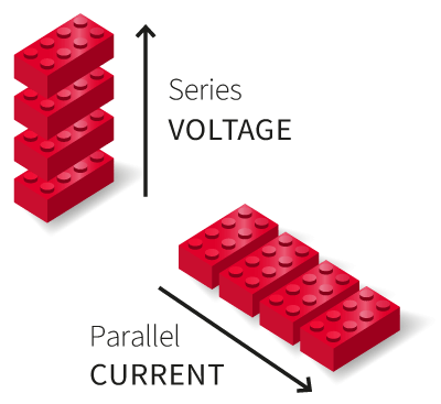
Modularization of the power stage
The modular implementation of the power stage provides superior flexibility and scalability over conventional designs.
Current ratings can typically be increased by placing PEBBs in parallel, while larger blocking voltages result from their connection in series.
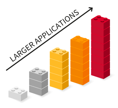
Scalability up to high power applications
PEBB-based modular power converters are often found in medium-voltage and high-voltage, high-power applications.
Scalability can, for instance, be pushed up to HVDC applications, thanks to the well-known Modular Multilevel Converters.
BACKGROUND AND REQUIREMENTS
MODULAR CONTROL SOLUTIONS FOR MODULAR POWER CONVERTERS
In response to the growing modularization of the power stage, some modularization of the control stage is required too! In practice, building large and/or complex digital control systems by simply assembling standardized control devices is uneasy. There several challenges to that:
UNIVERSALITY The modular construction of the controller must be transparent to the user. This means that all signals must be precisely time-coherent, at least as much as for a monolithic controller. Therefore, excellent synchronization accuracy is of utmost importance.
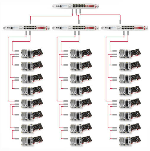
SCALABILITY The modular control system must be usable up to a large number of interconnected devices, typically one thousand. As such, simple wiring that also guarantees galvanic isolation is critical. Optical fibers must be used, with one single link per device.
PERFORMANCE With the same objective of transparency, identical closed-loop control performance must be achieved by the modular solution as by the monolithic alternative. Therefore, communication latency must not impact the overall control delay, at least not significantly.
RELIABILITY The networked nature of the modular control system must not impede the reliability of the overall system. Thus, data transfer determinism must be enforced and effective fault detection mechanisms must be in place.
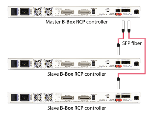
Elementary example using three stacked imperix controllers, interconnected using optical fibers.

Main challenges related to the modular design of power electronic control systems.
CLOSING FAST CONTROL LOOPS ANYWHERE ON THE NETWORK
One aspect of distributed converter control is particularly important so that the modularized controllers can be a true alternative to monolithic controllers. It is that the communication is sufficiently fast for supporting control loops that are closed across the network. In other words, inputs and outputs from anywhere on the network should not suffer from extra delays comparatively to a monolithic controller.

Fast local control loops
Local measurement inputs and modulator outputs can be used for local control loops.
Fast global control loops
Remote I/Os can also be involved in closed control loops, essentially with the same control bandwidth as local loops.
EXISTING LOW LATENCY COMMUNICATION TECHNOLOGIES
STATE OF THE ART
Existing networked control technologies
Widespread industrial communication protocols such as EtherCAT can be implemented for some control-related tasks in power electronics. For instance, exchanging measurements or setpoints is easy to implement. However, EtherCAT cannot provide low-latency data transfers, mostly due to the limited link speed. As such, this protocol cannot be involved within high-performance closed control loops.
In this context, protocols specific to power electronics emerged, such as PESnet and SyCCo (see table below), which provide much lower node-to-node latencies. That said, despite their superior performance, these protocols aren’t still well suited for large networks. Indeed, since the total latency increases linearly with the number of nodes, it quickly becomes excessive for closed-loop control purposes.
Imperix RealSync network and protocol
The imperix RealSync protocol offers an alternative to existing communication technologies, which guarantees low-latency communication within small- and large-size networks (up to thousands of nodes). Simultaneously, our protocol is also combined with the best synchronization accuracy available yet for power electronic applications, namely ±2ns.
The key features of RealSync are:
- Node latency of 170 ns
- Total latency increasing with 2log(#nodes)
- High synchronization accuracy of ±2ns
- Tree-shaped network topologies (n-tree)
- Up to 4096 addressable devices
- Fast gather/scatter DMA access for CPUs
- Re-configurable during run-time
 |  |  |  | ||
| EtherCAT | PESnet | Cust. Ethernet | SyCCo | RealSync | |
|---|---|---|---|---|---|
| Medium speed | 125 Mbps | 125 Mbps | 1.25 Gbps | 1.25 Gbps | 6.6 Gbps |
| Intended network topology | Ring | Ring | Any (eg. mesh) | Ring | Tree / pyramid |
| Best synchronisation | ± 1 μs / ± 20 ns | ± 40 ns | ± 4 ns (SyncE) | ± 4 ns | ± 2.0 ns |
| Typical node latency | > μs | < μs | > μs | < μs | < μs |
| Typical number of nodes | 10 < x < 1000 | < 50 | 10 < x < 1000 | < 50 | 2 < x < 5000 |
TECHNOLOGY INSIGHT
CHANGE OF PARADIGM IN SERIAL COMMUNICATION
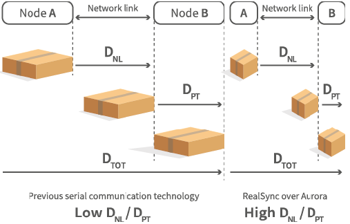
There are two essential figures to analyze in order to fully understand why RealSync is fundamentally different from alternative technologies.
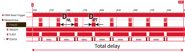
- DNL, designating the delay of the node latency. It represents how much time data packets require to travel from one node to the next.
- DPT, representing the delay due to packet transfer. This corresponds to how much time a device (e.g. FPGA) requires to process a data packet from its input to its output.
With older communication technologies and data processing devices, DNL used to be lower than DPT. In other words, most of the delays were located inside the devices and not the links between them. Nowadays, this paradigm has changed. Typically, FPGA devices have progressed much faster than communication links, which somewhat suffer also from physical limitations. For instance, as shown in the table below, when comparing RealSync with PESnet, DNL was reduced by a factor of 3, while DPT was reduced by a factor of 47!

” We’ve observed that FPGA technology offers game-changing opportunities for ultra-low-latency transfers in control systems, which is what we are exploiting.”
Lead FPGA engineer, imperix Ltd, Switzerland
Increased FPGA performance for faster processing
With recent technology advances, data processing delays inside FPGAs have been reduced drastically. They are now significantly lower than the packet travel time from node to node.
Xilinx Aurora with specialized packet routing
Our protocol uses the proven Xilinx Aurora 8b/10b layer 2 protocol, with intelligent packet switching for best-in-class performance. Furthermore, packet aggregation is also used to optimize the protocol efficiency.
| PESnet | SyCCo | RealSync | ||
|---|---|---|---|---|
| Speed | 125 Mbps | 1.25 Gbps | 6.6 Gbps | |
| DNL | 460 ns | 390 ns | 170 ns | x3 |
| Frame efficiency | 89 % | 97 % | 80 % | |
| DPT | 2880 ns | 264 ns | 61 ns | x47 |
| DNL / DPT | 0.16 | 1.36 | 2.79 | x17 |
TECHNOLOGY INSIGHT
USING THE MOST EFFECTIVE NETWORKING TOPOLOGY
With the evolution of the DNL/DPT ratio (see above), some hints are given that communication could be arranged somewhat differently.
Intuitively, when most delays occur inside the devices, it becomes obvious that the network itself isn’t fully utilized. By introducing the concept of topology efficiency (ET), this can be quantified as the percentage of time during which the communication links are used. Then, studying ET as a function of the network topology, it can be concluded that radial networks – i.e. tree-shaped – offer superior efficiency.
Intuitively, this can be relatively easily understood (as long as data congestion does not occur). Indeed, within a tree-shaped network, the longest path is proportional to the number of levels (i.e forks along the path) rather than the number of nodes. The closer are the slaves from the master, the shorter the delay.

RING NETWORK
1-tree (1 slave per node)

DAISY-CHAIN
1-tree (1 slave per node)

RADIAL NETWORK
2-tree (2 slaves per node)
TAKING ADVANTAGE OF A VERY PARTICULAR DATA TRAFFIC
The typical data traffic between distributed converter controllers is constituted by numerous small packets, which are exchanged at a relatively high frequency (up to >100kHz). In such a case, the overall network is best used when its nodes are interconnected by forming a pyramidal network.

Thanks to our unique tree-shaped control network, we can take the most of the improved DNL / DPT ratio, in other words, of the newest FPGA technology.
Chief of engineering, imperix Ltd, Switzerland

Topology is indifferent for very large payloads, but 2-tree is more than twice better for 25-40 Bytes!
Conventional high-speed serial communication
- 1-tree network topology (e.g. ring or string)
- Poorly exploited DNL / DPT ratio
Packets are processed one after the other. Therefore, the total delay corresponds to N+1 hops, which is close to the number of nodes N.
Low-latency communication with RealSync
- 2-tree network topology
- Takes advantage of high DNL / DPT
Packets that converge towards the master are aggregated. Besides, the total delay is proportional to the number of levels (rather than nodes).
LOW-LATENCY DATA EXCHANGE
KEY PERFORMANCE FIGURES
The two figures below demonstrate the achieved performance with imperix’s proprietary RealSync communication protocol. They notably show that, taking advantage of the particular type of data traffic involved in power electronic control applications, extremely low latencies can be achieved.
6.6 Gbps, N8

Sub-microsecond transfers up to eight nodes!
When depicting the longest delay DTOT versus the packet size for different quantities of nodes N, it can be seen that the measured DTOT remains below the threshold of 1µs for up to 70 Bytes.
6.6 Gbps, 2-tree

Getting the most from the network topology
When comparing 2-tree networks with 1-tree networks, it can be observed that about twice lower latencies can be achieved for small payload sizes. This obviously leads to twice higher achievable interrupt rates!
BEYOND LOW-LATENCY COMMUNICATION
ADDITIONAL BENEFITS OF REAL SYNC
REALSYNC IS FULL-DUPLEX
Very importantly, with RealSync, upstream and downstream data exchanges are entirely independent. For instance, this means that ADC data coming from remote measurement and PWM parameters can be exchanged simultaneously.
This pushes even further the achievable performance, for instance by overlapping several interrupt cycles (see below).

BASIC SAMPLING SCENARIO

DOUBLE-RATE SAMPLING SCENARIO
REALSYNC PROVIDES SYNCHRONIZATION
Precise timing across all nodes requires that they are accurately synchronized. This is also essential for pulse-width modulation (PWM).
Clock dissemination is also part of the RealSync technology, which guarantees nanosecond-scale synchronization among all nodes.

DISTRIBUTED CONVERTER CONTROL IMPLEMENTATION
APPLICATION EXAMPLES
Here are some examples of distributed converter control strategies, implemented using imperix products.
DISTRIBUTED CONTROL OF MMC
Distributed MMC inverter control
The control of Modular Multilevel Converters is a well-known example of a very demanding application, which requires a rigorous control hierarchization.
For instance:
- Global control loops (e.g. grid currents/voltage) are executed in the top controller (master).
- Faster control loops (e.g. arm currents/energies) are run within phase controllers (masters).
- Submodules possess local controllers for management and/or control purposes (slaves).
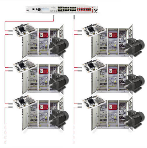
DISTRIBUTED DRIVES
Distributed inverter drives
When multiple electric motor drives must be coordinated, for instance for distributed traction, control hierarchization is essential.
For instance:
- Current and/or torque control is executed locally, within fast control loops.
- Speed and/or power control is executed globally, at a slower rate.