DISTRIBUTED CONVERTER CONTROL
ADVANCED POWER ELECTRONICS CONTROL SOLUTIONS
Modular power converter control for superior performance and flexibility
Thanks to the RealSync technology, the B-Box 4, the B-Box RCP 3.0 and B-Board PRO (incl. TPI8032) support the implementation of distributed converter control techniques over the network.
Indeed, control devices can be easily interconnected to form advanced control solutions and implement all sorts of control loops, executed centrally or in a distributed fashion.
Imperix distributed converter control solutions in three points
With the B-Box 4, B-Box RCP 3.0 and B-Board PRO, flexible and scalable control systems can be implemented by simply stacking hardware units, or arranging them in more complex configurations. In essence, our distributed converter control solutions rely on three pillars:
What is distributed converter control?
Distributed control refers to various arrangements of control (sub)systems that rely on some sort of communication between them.
Consequently, distributed converter control systems distinguish by implementing several processing devices (e.g. DSP, FPGA), at different structural or hierarchical locations.
ONE TECHNOLOGY FOR MULTIPLE OBJECTIVES
Distributed control is applicable to numerous scenarios. Two smart inverters exchanging some information is already some sort of distributed control. Alternatively, a large converter controller with a high number of I/Os probably also requires several FPGAs, and therefore some distribution of the control.
In all cases, thanks to the imperix RealSync technology, there are virtually no limitations to how devices can be interconnected to form more advanced converter controllers.

CENTRALIZED CONTROL
Centralized control designates controller arrangements where all control loops are closed through the same processing device.
As such, all data are retrieved up to some central point. Besides, slave units are not contributing significantly to the control.
- Low-complexity systems
- Laboratory converter prototypes
- Interleaved systems (conventionally)

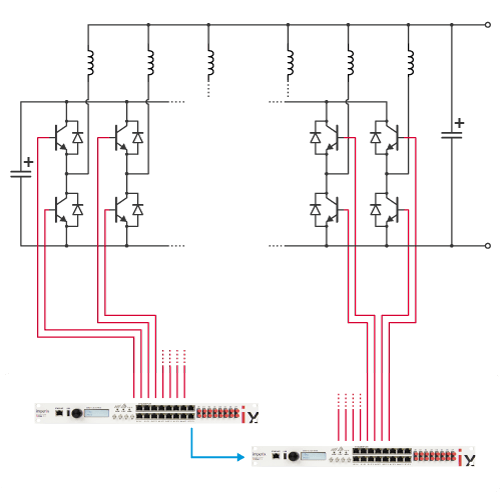
COORDINATED CONTROL
Coordinated control occurs when multiple controllers exchange some data but remain essentially independent.
Therefore, coordinated control typically implements several control loops, which are closed in different processing devices.
- Back-to-back inverters
- Microgrid (smart) inverters
- Distributed motor drives (e.g. traction)

HIERARCHIZED CONTROL
Hierarchized control refers to systems that possess various local and global control loops, closed in different locations.
In practice, control hierarchization is often used to balance the computational burden and/or reduce data exchanges.
- Modular Multilevel Converters
- High-performance motion control
- Paralleled inverters (to some extent)
NETWORKED CONTROL SOLUTIONS
FLEXIBLE CONTROL ARCHITECTURES
The above-described distributed control solutions naturally implement various types of data exchanges between the controller units. Imperix distinguishes three different interconnection modes for its RealSync compatible programmable controllers. In essence, there are three possible types of communication:
- The I/O extension mode is the easiest to use as it only requires to interconnect control devices with an SFP fiber and flash some code in the master. Slaves can be instantly addressed entirely transparently from the peripheral blocks in Simulink/PLECS/C code.
- The parallel mode operates through CAN or Ethernet. Therefore, it requires that the control software is developed, on both sides, for sending or receiving specific information. There are specific I/O blocks for that.
- The combined mode benefits from both approaches. Vertical exchanges are handled transparently (using the device ID), while horizontal exchanges use SFP/CAN/ETH blocks directly from within the user file or code.
I/O extension mode
MASTER-SLAVE
The slave devices only operate as I/O extension units for the master. As such, only their FPGAs are operating.
This mode only supports centralized control.
| Max. num. of masters | 1 |
|---|---|
| Max. num. of slaves | 64 |
| CPU-to-CPU communication | N/A |
| CPU-to-FPGA communication | Native (RealSync) Slaves addressing mode |
| Synchronization | Native (RealSync) |
| Exchange direction | Vertical only |
Parallel mode
MASTER-MASTER
Master devices exchange data in order to mutually influence their operation. CPUs on both sides are active.
This mode is useful for coordinated control.
| Max. num. of masters | Unlimited |
|---|---|
| Max. num. of slaves | N/A |
| CPU-to-CPU communication | CAN/Ethernet |
| CPU-to-FPGA communication | N/A |
| Synchronization | Not available |
| Exchange direction | Horizontal only |
Combined mode
MASTER-MASTER-SLAVES
Both I/O extension and parallel modes are simultaneously active. Various types of data exchanges occur, often at different rates.
This mode is required for hierarchized control.
| Max. num. of masters | 16 |
|---|---|
| Max. num. of slaves | 16×64=1024 |
| CPU-to-CPU communication | SFP (RealSync) Also ETH/CAN (slower) |
| CPU-to-FPGA communication | Native (RealSync) Slaves addressing mode |
| Synchronization | Native (RealSync) |
| Exchange direction | Vertical + Horizontal |
I/O EXTENSION MODE
MASTER + SLAVE OPERATION

Easy-to-use centralized control architecture
In this mode, there is only one control file/project (e.g. Simulink file) to edit, update and debug. Also, all measurements and variables are accessible at one point. This greatly simplifies the simulation and debugging during control software development. In this mode:
- Only the master has its CPU operating
- All FPGAs are tied to the same CPU (inside the master)
- Communication and synchronization are native (RealSync over SFP)

CONTROL SOFTWARE
- Only one converter controller exists
- Only one control executable is needed (e.g. Simulink file or C/C++ project)
- CPU processing performance is often sufficient, even for complex algorithms
- Multi-rate control is already possible in this mode, thanks to different interrupts

COMMUNICATION
- Data exchanges between master and slaves uses imperix’s RealSync protocol
- No configuration is needed. All data are automatically sent from/to the master
- Data exchanges are full-duplex and entirely deterministic
- Latency is extremely low (largely sub-us)

SYNCHRONIZATION
- Slaves operate in the same clock domain as the master
- No configuration is needed. All slaves are automatically synchronized
- Synchronization accuracy is ±2ns
PARALLEL MODE
MULTI-MASTER OPERATION
The conventional approach for coordinated control
This is the most usual way to implement distributed converter control. Since both masters are executing their own converter control file/project (e.g. Simulink file), the latter must manage the communication explicitly. On the other hand, since the communication makes use of non-proprietary protocols (e.g. CAN/Ethernet), this mode is also able to interface with third-party products and devices.

In this mode:
- Each master has its CPU operating
- Each FPGA is tied to its neighboring CPU
- Only basic synchronization is available (IEEE1588)
- Data exchanges use from/goto functions or blocks
CONTROL SOFTWARE
- Distinct controllers are implemented
- Each controller requires its own control file (Simulink or C/C++).
- Distributed control can be implemented, even when controllers are independent
- The overall computation capability is proportional to the number of units
COMMUNICATION
- Data exchanges between devices are made using Ethernet or CAN (flexible)
- Communication is user-configured using from/goto function blocks
- Data transmission delays vary with traffic
- Latency is significant (can be >100µs)
SYNCHRONIZATION
- Devices operate in different clock domains
- RealSync is not available (SFP only)
- Synchronization can be achieved using IEEE1588, but with limited accuracy
COMBINED MODE
MULTI-MASTER OPERATION WITH SLAVES

Elementary distributed converter control
When Ethernet or CAN is used for horizontal communication, distributed converter control is possible, but accurate synchronization is not available.
In this mode:
- Each master has its CPU operating
- Each FPGA is tied to its neighboring CPU
- Only poor synchronization is available (IEEE1588)
- Data exchanges use from/goto functions or blocks

A boundless range of hierarchized control solutions
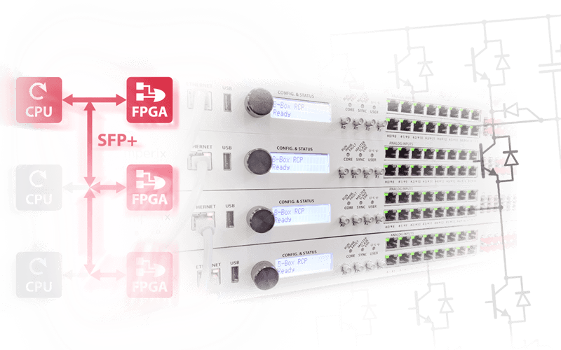
When the SFP fibers and the RealSync protocol are used for horizontal communication, all converter control units are natively synchronized. Besides, much faster – and full deterministic – data transfers are also guaranteed.
In this mode:
- Each master has its CPU operating
- FPGAs are tied to their respective masters
- All units are natively and perfectly synchronized
- All data exchanges use SFP+ (galvanically-isolating fibers)
CONTROL SOFTWARE
- Distinct controllers are implemented
- Each master+slaves group requires a control file (Simulink or C/C++)
- Control can be distributed or hierarchized among complex controllers
- The overall computation capability is a function of the number of masters
COMMUNICATION
- Data exchanges inside master-slaves groups are transparent (I/O extension).
- Exchanges between masters is user-configured with from/goto function blocks
- SFP offers widely superior performance over CAN/Ethernet
- Latency is extremely low with RealSync
SYNCHRONIZATION
- All devices are in the same clock domain
- No configuration is needed. All slaves are automatically synchronized to the master
- Synchronization accuracy is ±2ns
DISTRIBUTED CONVERTER CONTROL IMPLEMENTATION
APPLICATION EXAMPLES
Here are some examples of distributed converter control strategies, implemented using imperix products.
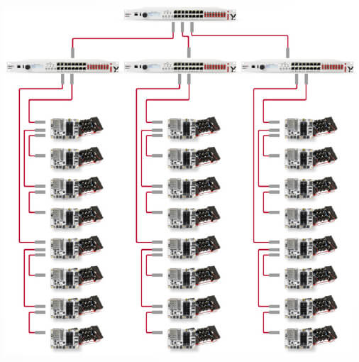
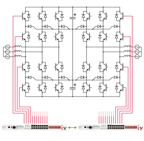
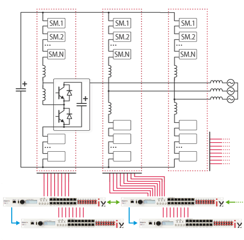
DISTRIBUTED CONTROL OF MMC
Distributed MMC inverter control
The control of Modular Multilevel Converters is a well-known example of a very demanding application, which requires a rigorous control hierarchization.
For instance:
- Global control loops (e.g. grid currents/voltage) are executed in the top controller (master).
- Faster control loops (e.g. arm currents/energies) are run within phase controllers (masters).
- Submodules possess local controllers for management and/or control purposes (slaves).
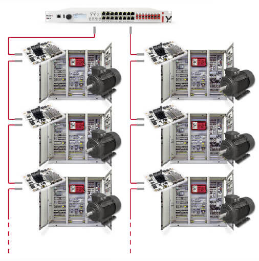
DISTRIBUTED DRIVES
Distributed inverter drives
When multiple electric motor drives must be coordinated, for instance for distributed traction, control hierarchization is essential.
For instance:
- Current and/or torque control is executed locally, within fast control loops.
- Speed and/or power control is executed globally, at a slower rate.