Table of Contents
The UDP output mailbox block allows sending up to 1024 bytes of data via Ethernet using the UDP/IP protocol (in SDK versions prior to 2025.2, the size limit is 8 bytes). To receive data, the UDP input mailbox should be used. Alternatively, for exchanges based on explicit read or write requests through a standardized register-based interface, the Modbus TCP output mailbox can be used instead.
The data to send via UDP is formatted as a vector. The Signal decoding format parameter defines the data type of each element, and the Number of signals parameter defines the length of the output vector. The data can be interpreted as one of the following types: int8, int16, int32, uint8, uint16, uint32, float32, or float64.
Example: if Signal decoding format is set to uint32 (4 bytes) and Number of signals is 100, then:
- Size of the UDP data = 4 × 100 = 400 bytes
- Output = vector of 100 uint32 elements
The block supports two Data transmission mode:
- On-demand: the user manually triggers the message transmissions.
- Periodically: the message is sent periodically, whether the data has been changed or not. The user can configure the transmission frequency.
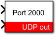
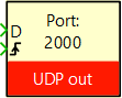
Simulink block
Signal specification
- The first input is the data to send. The accepted data type is specified by the Signal coding format parameter. This data can be provided as a vector, with its size defined by the Number of signals parameter.
- The second input is the send data signal. It is used to initiate a data transmission when the Data transmission mode is set to On-demand mode has been selected. Data is sent upon a rising edge on this signal.
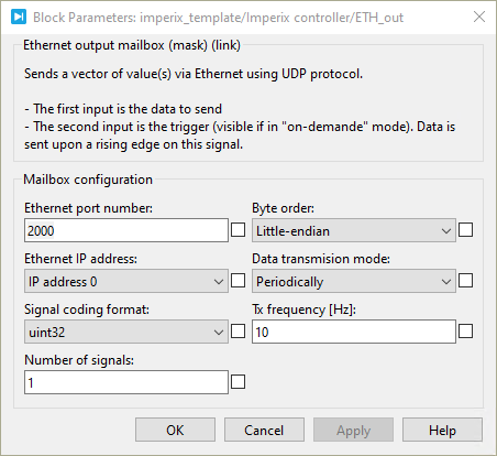
Parameters
- Ethernet port number: sets the destination port to which the data will be sent.
- Ethernet IP address : selects the IP address to whom the data will be sent.
- Signal coding format: defines the data type accepted in the data input (int8, int16, int32, uint8, uint16, uint32, float32, or float64).
- Number of signals: specifies the vector size of the data to be sent.
- Byte order : defines the byte order in which the data will be sent. (Little-endian or Big-endian)
- Tx frequency : sets the data transmission frequency if the Data transmission mode is set to Periodically.
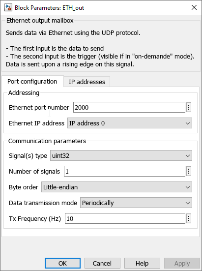
PLECS block
- The first input is the data to send. The accepted data type is specified by the Signal coding format parameter. This data can be provided as a vector, with its size defined by the Number of signals parameter.
- The second input is the send data signal. It is used to initiate a data transmission when the Data transmission mode is set to On-demand mode has been selected. Data is sent upon a rising edge on this signal.
Parameters
- Ethernet port number: sets the destination port to which the data will be sent.
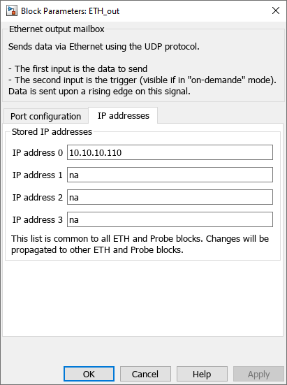
- Ethernet IP address : selects the IP address to whom the data will be sent.
- Signal coding format: defines the data type accepted in the data input (int8, int16, int32, uint8, uint16, uint32, float32, or float64).
- Number of signals: specifies the vector size of the data to be sent.
- Byte order : defines the byte order in which the data will be sent. (Little-endian or Big-endian)
- Tx frequency : sets the data transmission frequency if the Data transmission mode is set to Periodically.