Table of Contents
At the hardware level, GPI inputs are general-purpose digital inputs that can be configured for various purposes. This block and the associated C/C++ routines provide means to read the value of the corresponding pin at the CPU execution rate. For FPGA users, GPI pins are also available in the sandbox, enabling faster sampling rates.
The table below outlines the location and logic-voltage levels of the FLT inputs across imperix controllers. Detailed information is available in the product datasheets. For the TPI8032, using the TPI GPI helper block is recommended instead.
| Param. | B-Box 4 | B-Box 3 | B-Box micro | B-Board 3 PRO |
|---|---|---|---|---|
| Location and count | 24x VHDCI A | 16x VHDCI A+B | 8x rear connector | 16x JX1+JX2 (bot.) |
| Logic level | 3.3V / 5V | 3.3V / 5V | 5V | 3.3V |
| Shared with | FLT | N/A | N/A | N/A |
| Product datasheet | B-Box 4 | B-Box 3 | B-Box 3 micro | B-Board 3 |
Simulink block
Signal specification
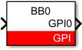
The output signal returns the value of one GPI pin.
Parameters
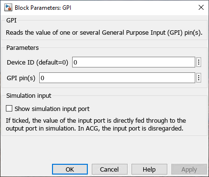
Device IDselects which B-Box/B-Board to address when used in a multi-device configuration.GPI pin(s)(vectorizable) a selection of GPI pin(s) to read. It can be a single value or a vector.Show simulation input portdefines whether the simulation input is displayed.
PLECS block
Signal specification
The output signal returns the value of one GPI pin.

Parameters
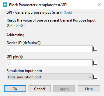
Device IDselects which B-Box/B-Board to address when used in a multi-device configuration.GPI pin(s)(vectorizable) a selection of GPI pin(s) to read. It can be a single value or a vector.Simulation input portdefines if the target inport is displayed or not. This parameter is only used in simulation.
 By Julien Orsinger • December 15, 2025 • PN134
 By Benoît Steinmann • April 2, 2021 • SD006