Table of Contents
The FLT block configures and reads the digital fault inputs.
The fault input pin signals are tied to the fault manager and, using the FLT block, they can be configured to generate a “hardware fault” and immediately disable all the PWM outputs (similar to an analog input limit fault or any other fault). They can also be accessed as digital inputs like a GPI.
The reference table below outlines the location, voltage logic levels and fault input counts, while detailed information regarding the fault inputs is available within the associated product datasheet.
| Param. | B-Box 4 | B-Box 3 | B-Box micro | B-Board 3 PRO |
|---|---|---|---|---|
| Location and count | – 24x VHDCI inputs | – 16x VHDCI inputs | Unavailable | – 16x PCB header inputs |
| Logic level | – 3.3V/5V | – 3.3V | N/A | – 1.8V |
| Shared with | – GPI | N/A | N/A | N/A |
| Product datasheet | B-Box 4 | B-Box 3 | B-Box micro | B-Board 3 PRO |
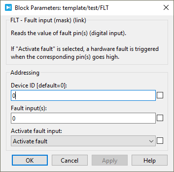
Simulink block
Signal specification
The output signal returns the value of one FLT pin.

Parameters
Device IDselects which B-Box/B-Board to address when used in a multi-device configuration.Fault input(s)(vectorizable) selects the pin(s) to read.Activate fault inputenable the generation of a “hardware fault” if the pin goes high and immediately disable all the PWM outputs.
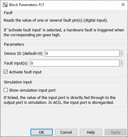
PLECS block
Signal specification
The output signal returns a vector containing the values of the FLT pins. The vector size is defined by the number of FLT pin(s) read which is specified by the parameter Fault input(s).

Parameters
Device IDselects which B-Box/B-Board to address when used in a multi-device configuration.Fault input(s)(vectorizable) selects the pin(s) to read.Activate fault inputenable the generation of a “hardware fault” if the pin goes high and immediately disable all the PWM outputs.