Table of Contents
The resolver interface block decodes the feedback from a resolver and provides the position of the rotor for drive applications.
The B-Box RCP supports up to two resolvers through the Motor Interface for B-Box RCP. Usually, a resolver-to-digital converter IC handles this type of sensor by generating the excitation signal (EXC) and extracting the position of the rotor from the quadrature signals (SIN and COS). The resolver module configures the dedicated IC inside the Motor Interface, including the excitation frequency and resolution, and retrieves the decoded position angle. The latter is latched similarly and simultaneously to the sample-&-hold feature of the ADC inputs. Additionally, the Motor Interface also provides the estimated rotation speed.
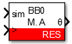
Simulink block
Signal specification
- The output signal is the mechanical angle in the range [0; 2π].
- The
siminput signal is used in simulation and represents the actual angle value in radian, computed by the simulation plant model. - The
>input signal needs to be connected to the sampling clock generated by the CONFIG block to account for the exact sampling instant in simulation.
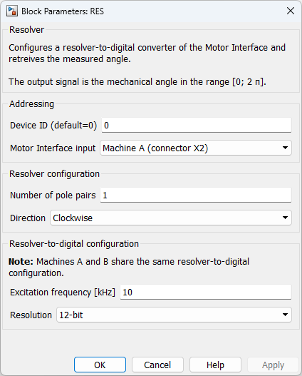
Parameters
Device IDselects which B-Box/B-Board to address when used in a multi-device configuration.Motor Interface inputselects which connector of the Motor Interface is used as an input.Number of pole pairsdefines the number of pole pairs of the resolver.Directiondefines if an increasing angle corresponds to a clockwise or counterclockwise rotation.Excitation frequencydefines the excitation frequency, in kHz. The excitation frequency admissible range depends on the resolution (cf. Excitation frequency admissible range section) and is set by increments of 250 Hz.Resolutiondefines the resolution of the acquired position (10, 12, 14 or 16 bits).
PLECS block
Signal specification
- The output signal is the mechanical angle in the range [0; 2π].
- The
siminput signal is used in simulation and represents the actual angle value in radian, computed by the simulation plant model. - The
>input signal needs to be connected to the sampling clock generated by the CONFIG block to account for the exact sampling instant in simulation.

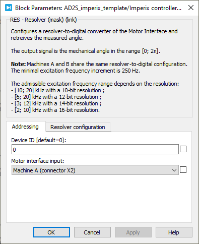
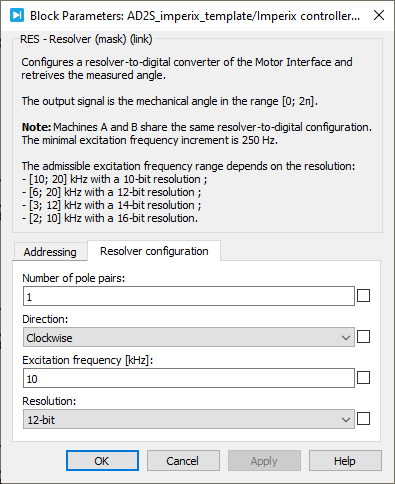
Parameters
Device IDselects which B-Box/B-Board to address when used in a multi-device configuration.Motor Interface inputselects which connector of the Motor Interface is used as an input.Number of pole pairsdefines the number of pole pairs of the resolver.Directiondefines if an increasing angle corresponds to a clockwise or counterclockwise rotation.Excitation frequencydefines the excitation frequency, in kHz. The excitation frequency admissible range depends on the resolution (cf. Excitation frequency admissible range section) and is set by increments of 250 Hz.Resolutiondefines the resolution of the acquired position (10, 12, 14 or 16 bits).
C++ functions
Excitation frequency admissible range
The admissible range of the excitation frequency depends on the resolution.
The excitation frequency must be within:
- [10; 20] kHz when the resolution is set to 10 bits;
- [6; 20] kHz when the resolution is set to 12 bits;
- [3; 12] kHz when the resolution is set to 14 bits;
- [2; 10] kHz when the resolution is set to 16 bits.
