
PLECS BLOCKSET
PART OF THE ACG SDK
The PLECS blockset contained within ACG SDK enables graphical converter control software design and implementation. It transforms imperix controllers into fully-compatible PLECS Coder targets.
The blockset takes advantage of both the simulation and code generation engines of PLECS to support easy converter control development and maintenance.

VOLUME PRICING
When multiple licenses are related to the same customer, degressive pricing applies, according to the overall purchase history. The table below shows the proposed volume discounts:
Volume discounts
| 2nd | 41% | 6th | 57% |
| 3rd | 49% | 7th | 59% |
| 4th | 53% | 8th | 60% |
| 5th | 55% | 9th | 61% |
PRODUCTION LICENSES
All controllers can be flashed up to 20 times with this free-of-charge license. This authorizes firmware upgrades during the entire system lifetime in production environments.
LICENSING POLICY
R&D LICENSES
These licenses allow unlimited access to the controllers. All software licenses are:
- Target-locked (i.e. tied to the controller unit)
- Lifetime (no renewal fees, free software updates)
- Usable on an unlimited number of computers
In multi-controllers configurations (B-Box 4, B-Box RCP 3.0 or B-Board PRO only), only the master unit must be licensed. The master is the controller hosting the user-defined CPU program.
PRODUCTION LICENSES
All controllers can be flashed up to 20 times with these free-of-charge licenses. This authorizes firmware upgrades during the entire system lifetime in production environments.
IMPERIX CONTROL HARDWARE AS A PLECS CODER TARGET
MAIN BENEFITS
- Ease of use: Accessible and fast graphical programming thanks to automated code generation.
- Accurate modeling: Advanced simulation models for faithful offline simulation results.
- Extensive capabilities: Broad range of specialized functions such as ADC, PWM modulators, etc…
- High performance: Transparent use of optimized driver methods for uncompromised performance.
- High flexibility: Easy integration with custom FPGA-based developments, offering boundless possibilities.

Start from scratch, adapt an existing control model, or use one of the code examples available on the imperix knowledge base.

You can test your control on a simulated converter model first. Then, you can rely on the obtained results to switch to real power.

In just one click, your model is automatically converted into code and executed on your imperix target, thanks to a fully integrated toolchain.

The transient generator and datalogging features of Cockpit will challenge your control and export the results for your next publication.
INTEGRATED CONTROL SOFTWARE DEVELOPMENT
The ACG SDK can integrate directly inside the PLECS environment, making rapid prototyping directly available from PLECS – standalone or blockset – which offers:
- A vast collection of PLECS native blocks
- Native libraries. Including electrical, thermal and magnetic libraries
- A powerful simulation and code generation engines
On the control side, the ADG SDK makes imperix controllers directly programmable from PLECS. Each block contains both a simulation model and its code counterpart for the real-time execution.
On the plant side, PLECS can be fully leveraged for running offline simulations and pre-tuning control parameters, making the transition from the computer to the lab quick and easy.
![]() Hover to find out more.
Hover to find out more.
EMBEDDED OPERATING SYSTEM
Thanks to the layered structure of the embedded operating system, PLECS has access to the exact same drivers as the C++ routines. This guarantees the best possible performance as well as a rigorous supervision of possible hardware misconfigurations.
FPGA CUSTOMIZATION
For demanding applications, parts of the runtime control can be offloaded inside the user-programmable portion of the FPGA. For this, PLECS has interface blocks readily available, exchanging data with the FPGA sandbox (SBI and SBO peripherals).
SOFTWARE LICENSING
The licensing policy of ACG SDK authorizes downloading and installing the software on an unlimited number of computers. As such, offline simulation is always possible. A license is only required to load and execute the control code onto a real-time control target (e.g. B-Box).
INTERFACE BLOCKS TO DEDICATED HARDWARE PERIPHERALS
The PLECS blockset included in ACG SDK contains numerous blocks to interface your PLECS model with any kind of I/O on imperix controllers. In particular, several PWM modulators are provided to fulfill the needs of the most demanding applications, whether it is for a traditional carrier-based or a more advanced multi-level modulator.
Each individual block can be parametrized using an easy-to-use configuration dialog. For instance, modulator carrier shapes, ADC gains or PWM dead-times can be modified in a few clicks. Each block also includes a help button that provides detailed documentation on its functionalities and its recommended usage in all sorts of applications.
![]() Hover to find out more.
Hover to find out more.
ANALOG TO DIGITAL CONVERTER
DIGITAL-TO-ANALOG CONVERTER
GENERAL-PURPOSE INPUTS
GENERAL-PURPOSE OUTPUTS
INPUT FROM SANDBOX
OUTPUT TO SANDBOX
INCREMENTAL POSITION DECODER
FAULT FEEDBACK INPUTS
CARRIER-BASED PWM
Conventional pulse-width modulators with fixed or variable phase-shift.
DIRECT OUTPUT PWM
Direct update of switching state output.
SPACE VECTOR PWM
Two- and three-level Space Vector modulator.
SANDBOX PWM
Configurator for custom modulators designed in the FPGA Sandbox.
SORT-&-SELECT PWM
Multilevel modulator and balancer for modular converter topologies (MMC and similar).
PROGRAMMED PATTERNS PWM
LUT- based modulators for pre-optimized patterns such as selective harmonic elimination (SHE).
ACCURATE CONTROLLER MODELING
Thanks to precise simulation models in every peripheral block, the behaviour of imperix controllers can be accurately anticipated, allowing you to test and tune control strategies offline. Ultimately, this means that the transition from simulation to real power is made as smoothly as possible.
To this end, we carefully modelled every aspect of the control loop, especially regarding its dynamic behaviour. This involves parameters such as the sampling instant or PWM phase-shift, but also the computation time of the algorithm or the conversion delay of the ADCs.
![]() Hover to find out more.
Hover to find out more.
BOTH CONTROLLER AND PLANT IN THE SAME MODEL
Imperix examples are systematically constructed with two parts:
The control subsystem is meant to be executed in real-time on the controller. As such, it contains the peripheral blocks and the control algorithms, which can be automatically translated into executable code.
The plant subsystem contains a simulation model of the controlled equipment. This enables the accurate closed-loop simulation of the complete setup. However, no code is generated for that part.
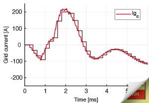
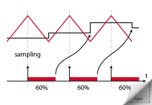
SAMPLING INSTANT
The ADC block combined with the sampling clock signal ensure that the measurements provided by the plant model are sampled at the correct frequency and with the right phase. This way, the simulated controller can work with the exact same discrete samples as a real controller.
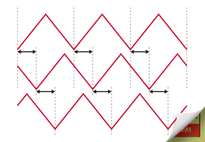
PWM PHASE-SHIFTS
The CB-PWM block lets you freely configure the phase-shift, even at run time. In addition, the corresponding simulation model uses a clock signal to guarantee a precise timing of the generated switching edges using the exact same logic as the real controllers.
COMPUTATION TIME
When applications grow in complexity, the computation time of the control algorithms introduces some delay in the control loop. This is very often neglected in RCP systems, but thanks to our simulation models, this can be anticipated and the control tuned accordingly.
ACCURATE PLANT MODELING
On the plant side, any existing simulation model can be used. That said, in order to facilitate the corresponding modelling efforts, the imperix PowerLib provides pre-implemented models for most power products. Building plant models is as simple as assembling the power modules themselves!


FREQUENCY MODELING
In order to faciliate the tuning of your control algorithms, the frequency-dependent behaviour of imperix products is accurately modeled.
Several levels of details are offered, corresponding to different trade-offs between accuracy and simulation complexity.

LOSSES MODELING
Both switching and conduction losses are accurately quantified, under various conditions, for most power products.
This enables the accurate anticipation of system-level efficiency, and is also necessary for the proper evaluation of the safe operating area of our power modules.

THERMAL MODELING
In order to precisely evaluate how much current can be carried under various operating conditions (e.g. as a function of the switching frequency, or under soft-switching conditions), the operating temperature must be evaluated.
Thermal simulation models of most power products is also included in the Power Library.
TO GO FURTHER
The ACG SDK – coupled with Simulink or PLECS – is able to cover a broad range of applications, while boosting the productivity of research engineers. This also relies on the powerful capabilities of additional software and tools.
Imperix Cockpit
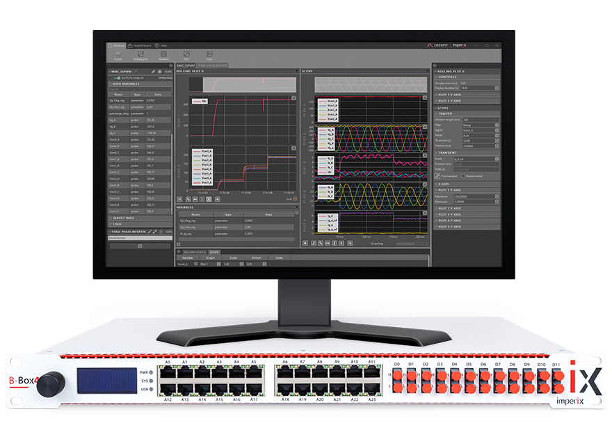
Cockpit is imperix’s real-time monitoring tool for B-Box and B-Board. This computer software allow viewing, editing and logging all control variables. Furthermore, Cockpit facilitates the configuration of the controllers.
- Real-time parameter tuning
- Data logging and visualization
To see how to extract impactful experimental results, get more insight on Cockpit.
FPGA programming
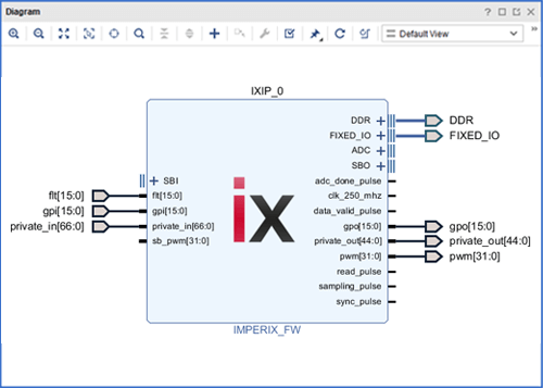
For the advanced cases when part of the control must be executed on FPGA, the firmware can be freely edited. Users only need to instantiate one imperix IP. Besides, all FPGA resources and I/Os can be accessed with complete freedom.
- Multi-rate control implementation
- Peripheral communication extension
To see how to extend the capabilities of imperix controllers, read more on FPGA programming.
Firmware technology
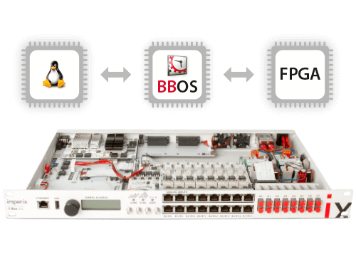
The acclaimed ease of use of imperix controllers is made possible by a dedicated firmware architecture. This also guarantees the portability of the user software as well as the advanced performance of the networking.
- Long-term code portability
- Transparent networking
To learn more about how the control hardware operates, see more details on our firmware.
RELATED PRODUCTS
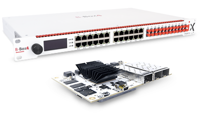
CONTROL HARDWARE
WANT TO KNOW MORE?
For all questions related to our software, feel free to get in touch with our technical team. We’re here to help! Online demos can also be organized upon request.
Alternatively, you can always download and install the software. As our licenses are hardware-related, our software is essentially unrestricted and all features can be tested free of charge.