Table of Contents
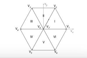
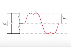
The SV-PWM block generates PWM signals based on the Space Vector Modulation (SVM) algorithm. This algorithm determines the three vectors that are the closest to the reference vector and computes the dwell times for each one. Based on those times, a duty cycle is computed and a triangular carrier is used to generate the PWM signal for each phase. The SVM method is explained in the Space Vector Modulation (TN145) and SVPWM vs SPWM modulation techniques (TN146) notes.
When using the single-rate update configuration, the computed duty cycles are synchronously applied at the end of the PWM period. With the double-rate update, the duty-cycle is updated twice per period: in the middle and at the end (in other words when the carrier reaches its maximum and when it reaches its minimum).
The frequency of the carriers is configured by connecting the SV-PWM block to a CLK – Clock generator. The frequency can even be tuned during the control execution as explain in Variable frequency operation with the B-Box/B-Board (PN121).
Like the other PWM blocks, the Space Vector Modulation block supports dead-time generation and can be activated or deactivated. More information is available on the PWM page.
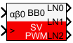
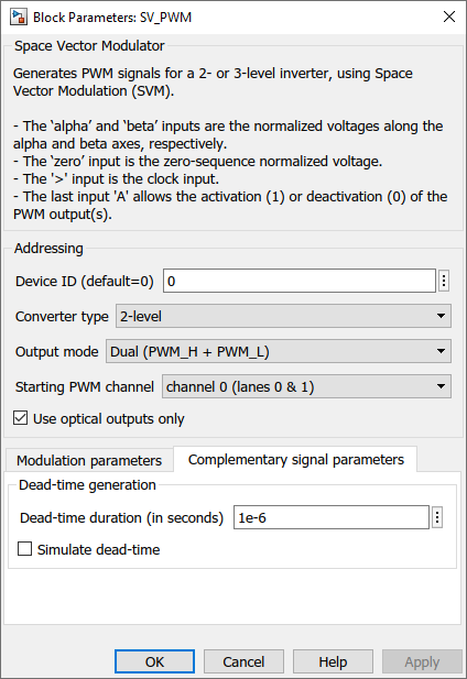
Simulink SV-PWM block
Signal specification
- The input
αβ0is the normalized reference vector in the stationary reference frame (-1.15 to 1.15). - The input signal
>is the clock input and must be connected to the CONFIG block or to an independent CLK. - The outputs are the generated PWM signals, according to the selected
output modeand theconverter type. The outputs are only used in the simulation.
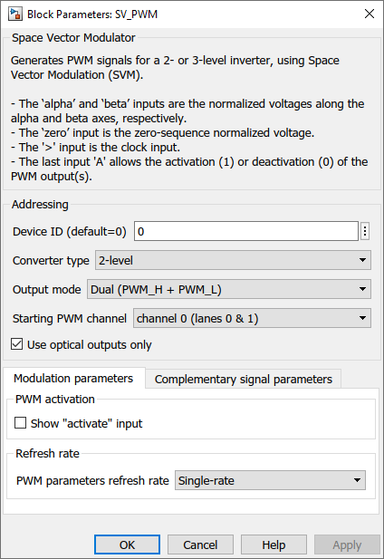
output mode, addressed PWM, dead-time and show ”activate” input are common to all PWM blocks and are further documented on the PWM page.Parameters
Device IDselects which B-Box/B-Board to address when used in a multi-device configuration.Converter typeconfigures the SV-PWM algorithm for a 2- or 3-level inverter.Output modeselects between a single PWM signal or complementary signals with a dead-time.Starting PWM channel: selects the first PWM output to be used for the set of PWM signals of the SV-PWM algorithm.Use optical outputs onlyselects if the PWM signals can be addressed only to the optical outputs, or if the electrical outputs (lanes 16 to 31) can also be used.Show ”activate” inputmakes theAsignal input visible. If not checked, the SV-PWM block is active by default.PWM parameters update rateselects when the duty-cycle and phase parameters are applied.- Single-rate: they are applied at the end of the carrier period.
- Double-rate: they are applied twice per carrier period: when the carrier reaches its lowest point and when it reaches its highest point.
Dead-time duration: configures the dead-time duration if theOutput modeis set at Dual (PWM_H + PWM_L).
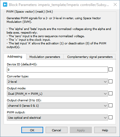
PLECS SV-PWM block
Signal specification
- The input
αβ0is the normalized reference vector in the stationary reference frame (-1.15 to 1.15). - The input
Aallows the activation (1) or deactivation (0) of the PWM output(s). - The input signal
>is the clock input and must be connected to the CONFIG block or to an independent CLK. - The target outport (only visible at the atomic subsystem level) are the generated PWM signals, according to the selected
Output mode(see PWM page for information). These outputs are only used in the simulation.

output mode, addressed PWM, dead-time and show ”activate” input are common to all PWM blocks and are further documented on the PWM page.Parameters
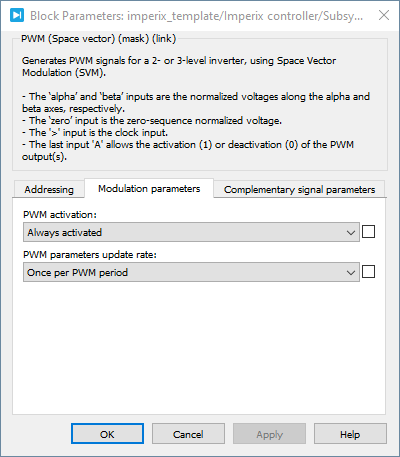
Device IDselects which B-Box/B-Board to address when used in a multi-device configuration.Converter typeconfigures the SV-PWM algorithm for a 2- or 3-level inverter.Output modeselects between a single PWM signal or complementary signals with a dead-time.Starting PWM channel: selects the first PWM output to be used for the set of PWM signals of the SV-PWM algorithm.Use optical outputs onlyselects if the PWM signals can be addressed only to the optical outputs, or if the electrical outputs (lanes 16 to 31) can also be used.Show ”activate” inputmakes theAsignal input visible. If not checked, the SV-PWM block is active by default.PWM parameters update rateselects when the duty-cycle and phase parameters are applied.- Single-rate: they are applied at the end of the carrier period.
- Double-rate: they are applied twice per carrier period: when the carrier reaches its lowest point and when it reaches its highest point.
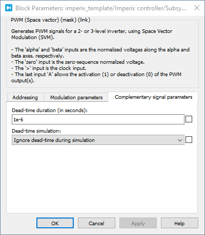
Dead-time duration: configures the dead-time duration if theOutput modeis set at Dual (PWM_H + PWM_L)
C++ functions
Specific to SV-PWM
Functions common to all PWM drivers
These functions are common to all PWM blocks. Further documentation is available on the PWM page.