Table of Contents
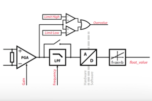
The ADC block (or C++ routines) are used to access data from a given Analog-to-Digital Converter (ADC) channel. They also serve to configure how this data is sampled, filtered, and rescaled, prior to being used inside the application-level user code. Together, these parameters constitute the so-called software part of the ADC channel configuration, as opposed to the hardware part.
The hardware part, on the other hand, also requires some configuration, whose details depend on the controller model. The table below summarizes these differences and provides direct links to the associated user guides. Comparative information about imperix’s programmable controllers is also given in PN250.
| Param. | B-Box 4 | B-Box 3 (RCP) | B-Box 3 micro | B-Board 3 (PRO) |
|---|---|---|---|---|
| Resources | – 24x 20Msps / 16bits – ±10V ADC range | – 16x 500ksps / 16bits – ±10V ADC range | – 8x 2Msps / 16bits – ±5V ADC range | – 8x 2Msps / 16bits – ±5V ADC range |
| HW param. | – Safety limits – Reaction speed – Calibration [Y/N] | – Input impedance – Safety limits – Pre-ADC gain – Low-pass filter | – Safety limits | N/A |
| SW param. | – Low-pass filter – Sampling method – Scaling (gain+offset) | – Sampling method – Scaling (gain+offset) | – Sampling method – Scaling (gain+offset) | – Sampling method – Scaling (gain+offset) |
| Doc. link | AI/AO config. | AI config. | AI config. | N/A (HW-dependent) |
Principles of operation
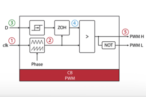
The sampling of all analog inputs is always conducted simultaneously, driven by SCLK, which is a simple derivative of CLK0, only differing by the SAMPLING_PHASE.
Both the freqency and the phase of the ADC sampling are defined from the CONFIG block. They set part of the overall timing configuration, which must be properly coordinated with modulation-related actions to guarantee the desired execution of the control algorithms. Notably, the two following options are possible:
- Single-rate sampling, in which case the control task is executed once per PWM period. This is the default configuration used in most examples.
- Double-rate sampling, in which case the control task is executed twice per PWM period, requiring ADC sampling to be executed twice faster than the modulation. This case gives best performance, provided that sufficient CPU time is available.
- Advanced sampling configurations are also possible, typically authorizing to retrieve multiple samples at once (data history), variable-frequency switching, or running FPGA-based control tasks at a higher rate than the CPU.
Frequency and phase aside, all other ADC parameters are individual, channel-specific settings that can be configured independently within each ADC block.
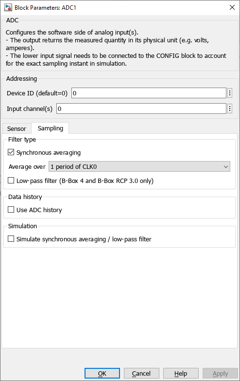
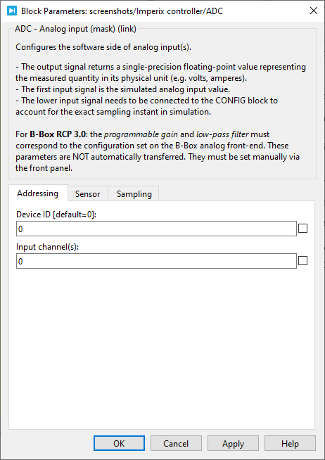
Block parameters
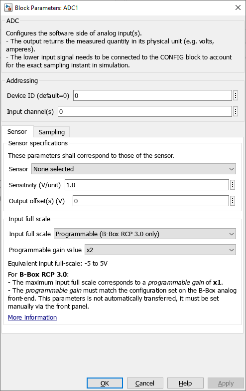
Addressing
- Device ID selects which device to address when used in a multi-device configuration.
- Input channel(s) (vectorizable) selects which physical input channel to read from.
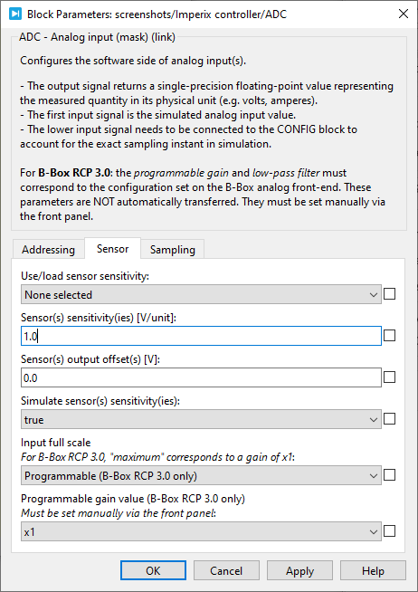
Sensor specifications
- The Sensor provides a list of imperix sensors. Selecting a sensor automatically populate the sensitivity parameter. When None is selected, the user must manually enter the sensitivity.
- Sensitivity (vectorizable) is the sensor sensitivity in Volts per measured unit (e.g. V/V for a voltage sensor and V/A for a current sensor).
- Output offset(s) (vectorizable) compensates for the sensor offset. It is expressed in Volts at the output of the sensor.
Input full scale
- The Input full scale parameter can be set to
- Maximum (device dependant)
- Programmable (B-Box 3 only)
- On the B-Box 3, the Programmable gain value can be set to 1x, 2x, 4x or 8x and must match the front panel setting.
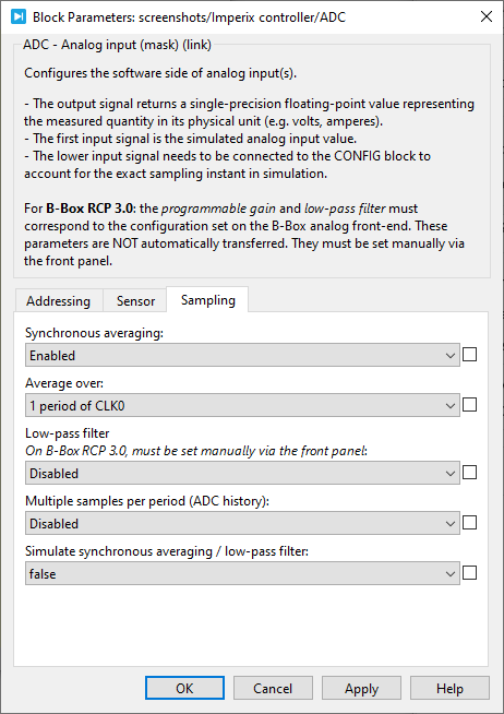
Sampling
- Synchronous averaging computes the average of multiple samples over a specific and synchronous time interval. The interval can be configured to 1 period of CLK0 or 2 periods of CLK0. This technique very effectively rejects high-frequency artifacts and is therefore enabled by default.
- A Low-pass filter is available in B-Box 3 and 4, providing a more aggressive attenuation in the high-frequency range. The chosen filter cut-off frequency may however introduce a non-negligible group delay, which should be accounted for in the control algorithm (and, ideally, the selection of the sampling phase).
For the B-Box 3 (RCP), the low-pass filter must be configured via the front panel, as shown in PN105. - Data history configures the block to output a vector of the N most recent ADC samples, which can be useful when the sampling frequency FSCLK is larger than the CPU task frequency FCPU. The maximum history depth is 64 samples.
- Simulate synchronous averaging / low-pass filter allows for a more accurate simulation, but it increases the simulation time.
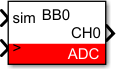
Simulink block
Signal specification
- The output signal returns a single-precision floating-point value representing the measured quantity in its physical unit (e.g. Volts, Amperes).
- The
siminput signal is used in simulation and documented in Simulation essentials with Simulink (PN135). - The
>input signal needs to be connected to the CONFIG block in order to account for the exact sampling instant in simulation.
Mask
PLECS block
Signal specification
- The output signal returns a single-precision floating-point value representing the measured quantity in its physical unit (e.g. Volts, Amperes).
- The target inport (only visible at the atomic subsystem level) is used in simulation and documented in Simulation essentials with PLECS (PN137).
- The
>input signal needs to be connected to the CONFIG block to account for the exact sampling instant in simulation.

Mask
C++ functions
ConfigureMainInterrupt function as explained in the related note: Interrupt configuration.