Table of Contents
The TPI ADC helper block is a wrapper that simplifies the use of the ADC block with the all-in-one programmable inverter (TPI8032 22kW). Since the topology of the converter is fixed, the channel assignment and the configuration of the built-in sensors are known beforehand.
The topology of the converter and the placement of the internal sensors is shown below. Additionally, the TPI features four analog inputs on its rear panel to support external sensors.
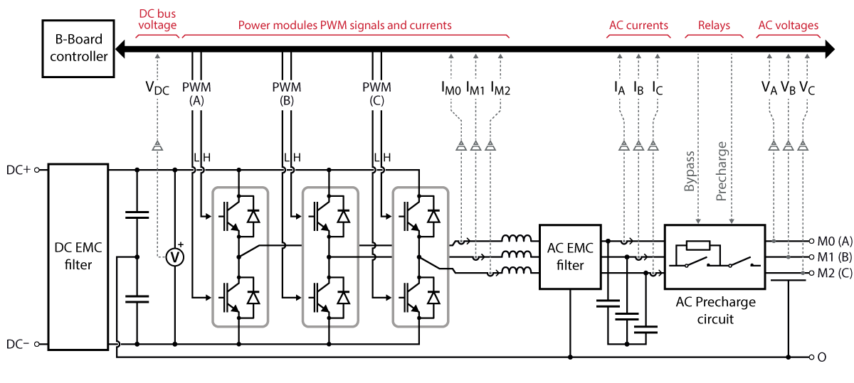
| Analog channel | Symbol | Description |
| 0 | Vdc | DC voltage |
| 9 | Ia | AC current – Phase A |
| 11 | Ib | AC current – Phase B |
| 13 | Ic | AC current – Phase C |
| 8 | Va | AC voltage – Phase A |
| 10 | Vb | AC voltage – Phase B |
| 12 | Vc | AC voltage – Phase C |
| 1 | IM0 | Power module current – M0 |
| 2 | IM1 | Power module current – M1 |
| 3 | IM2 | Power module current – M2 |
| 4 | AIN0 | External sensor #0 |
| 5 | AIN1 | External sensor #1 |
| 6 | AIN2 | External sensor #2 |
| 7 | AIN3 | External sensor #3 |
The TPI ADC helper block is available starting from version 2024.2 of the SDK. The TPI8032 is required to use this driver.
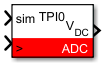
Simulink ADC helper block
Signal specification
- The output signal returns a single-precision floating-point value representing the measured quantity in its physical unit (e.g. Volts, Amperes).
- The
siminput signal is used in simulation and documented in Simulation essentials with Simulink (PN135). - The
>input signal needs to be connected to the sampling clock generated by the CONFIG block to account for the exact sampling instant in simulation.
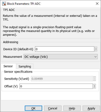
Parameters of the helper block
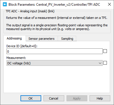
- Device ID selects which TPI to address when used in a multi-device configuration.
- Measurement selects which sensor to use.
- Sensor
- Sensor gives the option to load the parameters of an imperix sensor when using an external sensor.
- Sensitivity [V/unit] defines the sensitivity of the sensor. It is expressed in Volts per measured unit (e.g. V/V for a voltage sensor and V/A for a current sensor).
- Offset [V] defines the offset of the sensor. It is expressed in Volts at the output of the sensor.
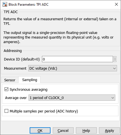
- Sampling
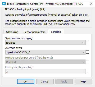
- Synchronous averaging configures the block to output the average ADC value over 1 or 2 periods of CLOCK_0. See Synchronous averaging for more details.
- Multiple samples per period (ADC history) configures the block to output a vector of the N last values. This option is mutually exclusive with the synchronous averaging.
PLECS ADC helper block
Signal specification
- The output signal returns a single-precision floating-point value representing the measured quantity in its physical unit (e.g. Volts, Amperes).
- The target input port (only visible at the atomic subsystem level) is used in simulation and documented in Simulation essentials with PLECS (PN137).
- The
>input signal needs to be connected to the sampling clock generated by the CONFIG block to account for the exact sampling instant in simulation.

Parameters of the helper block
- Addressing
- Device ID selects which TPI to address when used in a multi-device configuration.
- Measurement selects which sensor to use.
- Sensor parameters
- Sensor gives the option to load the parameters of an imperix sensor when using an external sensor.
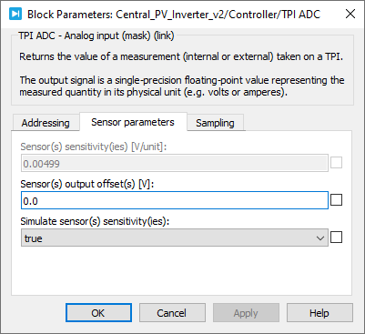
- Sensitivity [V/unit] defines the sensitivity of the sensor. It is expressed in Volts per measured unit (e.g. V/V for a voltage sensor and V/A for a current sensor).
- Offset [V] defines the offset of the sensor. It is expressed in Volts at the output of the sensor.
- Simulate sensor(s) sensitivity(ies): when true, the ADC block expects its input to be the value of the sensor’s output (typ. ±10V). When false, it expects the physical measure value.
- Sampling
- Synchronous averaging configures the block to output the average ADC value over 1 or 2 periods of CLOCK_0. See Synchronous averaging for more details.
- Multiple samples per period (ADC history) configures the block to output a vector of the N last values. This option is mutually exclusive with the synchronous averaging.
C++ functions
There are no C++ helper functions for the TPI. Please refer to the generic ADC functions.
