Table of Contents
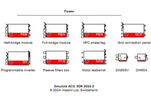
The MTB block is a simulation model included in the Imperix Power library. It models the imperix motor testbench in Simulink and PLECS simulation.
For more information regarding the Imperix Power library, please read Getting started with Imperix Power library.
• ACG SDK 2024.2: First release. Support for PLECS and Simulink SPS library (“Black” blocks).
• ACG SDK 2025.2: Addition of thermal models for most PEB and PEN modules.
• ACG SDK 2026.1: Support for the latest products (PEB-800-40, VSR-1000-ISO, VSR-500-HBW, CSR-25-HBW).
• ACG SDK 2026.1.3: Support for Simulink Simscape Electrical library (“Blue” blocks).
• Simulink (R2016a or newer): Simscape is required.
• Plexim PLECS (4.5 or newer): No particular requirement.
Additionally, for Simulink:
• Simscape Electrical library: Simscape Electrical is required.
• SPS library: Simscape Specialized Power Systems (up to R2025b) or OPAL-RT SPS Software is required.
Modeling of MTB
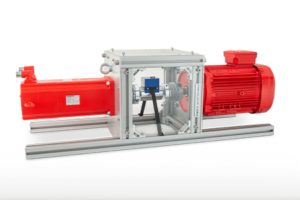
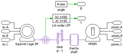
The Motor Testbench features a squirrel cage Induction Machine (IM) and a Permanent Magnet Synchronous Machine (PMSM). One machine is the device under test while the other one acts as a controllable load. The schematic is shown below.
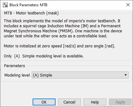
The MTB model has one modeling level:
- (A) Simple
For more detailed model parameters and measurement results, please contact [email protected].
Machine parameters
All the parameters of the machines are summarized in the following tables.
| Item | Symbol | Value |
|---|---|---|
| Pole pairs | p | 4 |
| Moment of inertia | Jm | 40.6e-4 kg.m^2 |
| Friction coefficient | kF | 30.35e-5 |
| Stator resistance | Rs | 0.559 Ω |
| Stator inductance | Ls | 4.24 mH |
| Stator inductance along d-axis | Ld | 4.24 mH |
| Stator inductance along q-axis | Lq | 4.24 mH |
| Flux from permanent magnets | Phi_pm | 0.2748 Nm/Apk |
| Item | Symbol | Value |
|---|---|---|
| Pole pairs | p | 4 |
| Moment of inertia | Jm | 178e-4 kg.m^2 |
| Friction coefficient | kF | 30.35e-5 |
| Stator resistance | Rs | 1.24 Ω |
| Rotor resistance | Rr | 0.73 Ω |
| Stator leakage inductance | Lgs | 11.5 mH |
| Rotor leakage inductance | Lgr | 11.5 mH |
| Mutual inductance | Lm | 183 mH |
| Item | Symbol | Value |
|---|---|---|
| Moment of inertia shaft | Jm_shaft | 54.7e-4 kg.m^2 |
Sensors
The motor testbench features an angle resolver and a torque sensor. The angle resolver is modeled by an ideal sensor with the angle initialized at 0, while the torque sensor is modeled by an ideal sensor with a 1kHz low-pass filter.
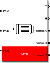
Simulink MTB block
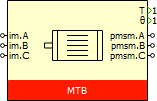
Port specification
- The output
Tis the measured torque. - The output
θis the measured rotor angle. - The connection ports
im.A,im.B,im.Care the electrical ports connected to the three-phase AC input of the IM. - The connection ports
pmsm.A,pmsmm.B,pmsm.Care the electrical ports connected to the three-phase AC input of the PMSM.
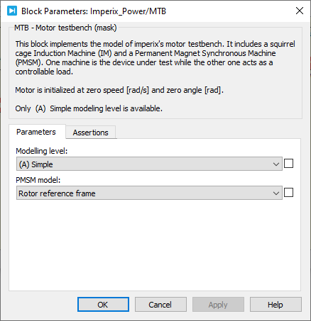
Parameters
Modeling levelselects the modeling level.
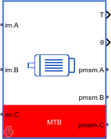
PLECS MTB block
Port specification
- The output
Tis the measured torque. - The output
θis the measured rotor angle. - The connection ports
im.A,im.B,im.Care the electrical ports connected to the three-phase AC input of the IM. - The connection ports
pmsm.A,pmsmm.B,pmsm.Care the electrical ports connected to the three-phase AC input of the PMSM.
Parameters
Modeling levelPMSM modelselects the model of PMSM. The PMSM can be either implemented in the rotor reference frame or as a voltage behind reactance.
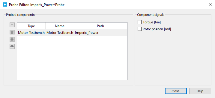
Probe signals
The following signals can be monitored by a Probe block in PLECS.
Torque [Nm]monitors the torque sensor output in Nm.Rotor position [rad]monitors the rotor position in rad.