Table of Contents
This note provides in-depth content for an accurate and efficient offline simulation of an imperix controller and the corresponding plant model using ACG SDK on Simulink.
Recommended articles related to the ACG workflow are shown below. A series of video tutorials is also available with similar content.
| Step | Documentation | Videos | |
|---|---|---|---|
| 1. Software installation | Installation guide for the ACG SDK PN133 | N/A | |
| 2. Getting started | Getting started with the ACG SDK PN134 | Create the model Video 1 | |
| 3. Running simulations | Simulation essentials with Simulink PN135 | Simulation essentials with PLECS PN137 | Simulate it Video 2 |
| 4. Device programming | Programming and operating imperix controllers PN138 | Generate code Video 3 | |
| 5. Monitoring | Cockpit user guide PN300 | ||
Fundamental concepts
The offline simulation is meant to faithfully reproduce the behavior of the overall system (controller and plant). To that end, the imperix blockset for Simulink was designed with the following guidelines in mind:
- The plant quantities are to be modeled with continuous signals
- This calls for using a variable-step solver
- The control algorithm is modeled with discrete signals, sampled at a rate equal to the interrupt frequency of the physical controller, and with a phase corresponding to the corresponding sampling phase.
- This requires a discretized algorithm (in \(z\) domain)
- This is modeled accurately with the variable-step solver, as it is forced to take a major step at each execution of the interrupt
- The behavior of the real PWM generators is modeled, in particular:
- The frequency and phase of the carrier
- The instants when the duty-cycle and phase parameters are updated (at zero and/or max of the carrier)
- The duration of the algorithm execution is modeled
- This induces a delay between the start of the interruption and the availability of the new data
With all the phases and delays modeled accurately, the simulated controller has the same dynamics as the real controller, which allows tuning the control parameters during the offline simulation.
The imperix blockset is already implemented such that these guidelines are automatically observed. As such, no particular action is required from the user.
Working principle of the main blocks
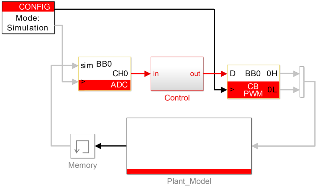
The three fundamental blocks are the Config, ADC, and PWM blocks. Most applications can work with only those three, as in the standard configuration shown below:
Configuration block and its clocks
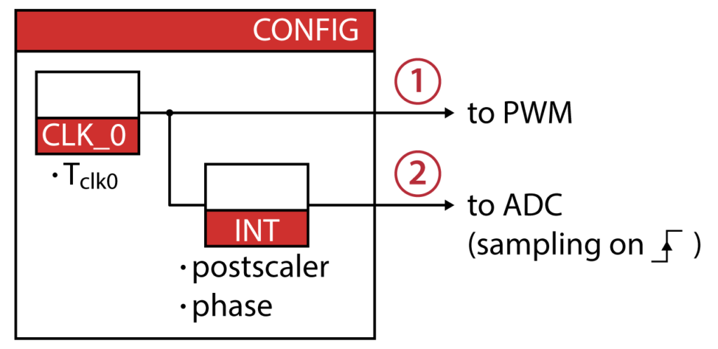
The Config block configures the main global parameters of the model, such as:
- The model execution purpose (offline simulation or code generation for a real-time target)
- The configuration of the default clock
CLK0, which is always used for sampling the triggering of the control interrupt. - Other advanced configuration parameters.
To configure and implement CLK0
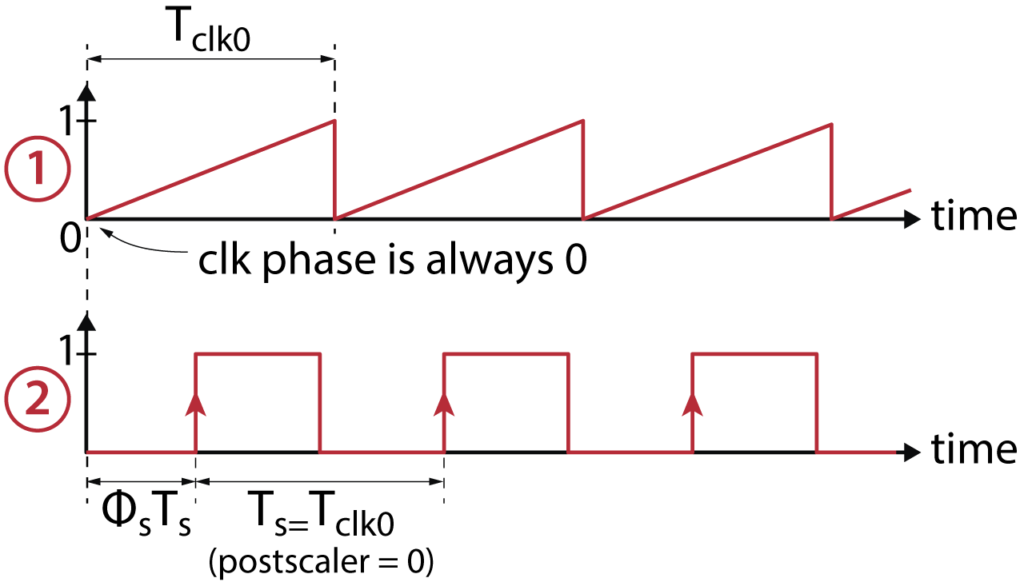
In simulation, the CLK block outputs a sawtooth signal with the clock period \(T_{clk0}=1/f_{clk0}\) and a phase of zero. Then, this clock signal is passed through a subsystem that generates a sampling clock, with a relative phase-shift of \(\phi_s\) and a period defined by:
$$T_s = \left\{ \begin{array}{ll} T_{\text{clk0}} & \text{if postscaler = 0}\\ \text{postscaler}\cdot T_{\text{clk0}} & \text{otherwise} \end{array}\right.$$
The Config block also sets the value of the sample time variable CTRLPERIOD. This variable can be used in any block requiring a sample time (e.g. discrete transfer functions):
$$\text{CTRLPERIOD} = \left[T_s, \phi_s T_s\right]$$
The fundamental elements of the Configuration block are mapped below, with the waveform of the generated signals.
ADC
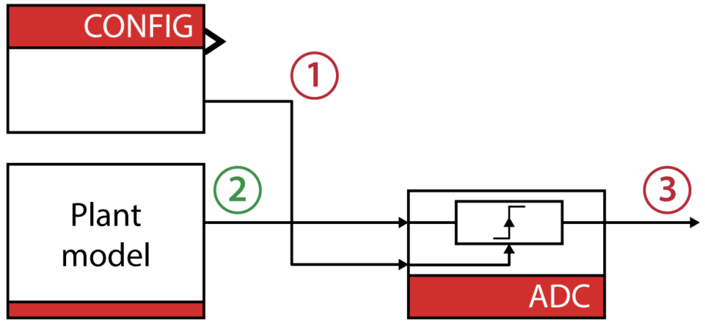
The ADC block allows retrieving the sampled value of a given ADC channel and converts it to its value in physical unit.
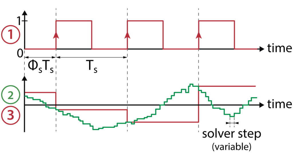
The simulation model simply sample-and-holds the input signal (2) with the rising edges of the sampling clock (1). The input signal is typically a continuous signal coming from the plant model and representing a measurement value. The sample time of the output signal (3) is set to CTRLPERIOD in order to be automatically propagated to other connected blocks.
PWM
Various types of pulse-width modulators exist within the imperix blockset. Among them, the carrier-based PWM modulator (CB PWM block) is probably the default and most generic one. It configures the corresponding FPGA peripheral and generates the PWM signals according to the duty-cycle and phase parameters.
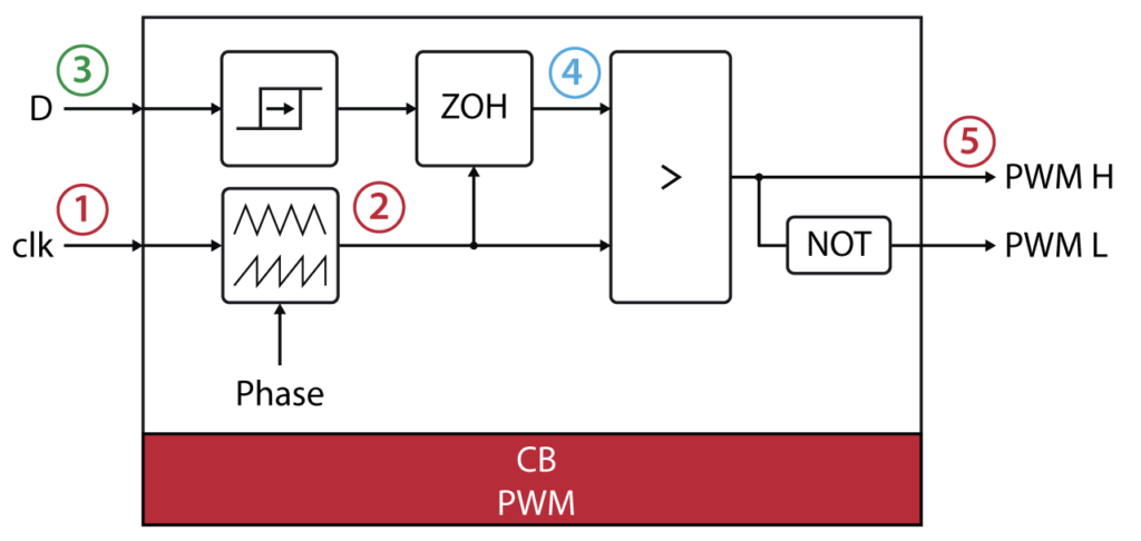
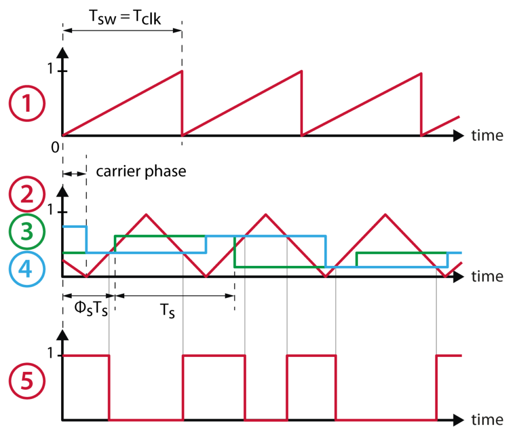
In the simulation model, the clock signal (1) connected to the clock input is used as a time reference to generate the carrier signal (2). In parallel, the duty-cycle value (3) is sampled (once or twice per switching period depending on the update-rate parameter) and compared to the carrier to produce the output PWM signal (5). (A more complex model is used to generate a carrier with a variable phase, which is beyond the scope of this document.)
Mastering the sample times
Mastering the sample time (essentially the execution rate) of each block is key for an accurate and efficient simulation of discrete control algorithms in Simulink, as well as the generation of proper run-time code. In particular, the execution rates must comply with the fundamental concepts listed above and be clearly identified by the Simulink Coder engine, namely:
- The plant (i.e. physical) signals are represented by continuous signals
- The control signals (i.e. those computed during the controller main interrupt) are represented by discrete signals with a sampling rate and phase corresponding to the configuration of the main interrupt. Their sample time is, therefore, the vector
CTRLPERIOD.
The blocks of the imperix blockset are built in such a way that they comply with these concepts. The user is only recommended to make sure that his/her control implementation is executed at the proper rate. In some situations, the CTRLPERIOD may not be propagated automatically to the whole control model (see the example of the step block below).
Verifying the sample times
In Simulink, the sample time of each signal can be conveniently displayed by choosing Display > Sample Time > Colors. The color legend can be displayed by pressing Ctrl+J (see below)
With the colors defined above, a typical control implementation should look like this:
As the ADC and PWM blocks serve as an interface between the continuous plant signals and the discretized control, they contain blocks with different sample times and have thus a Hybrid sample time.
Altering the sample times
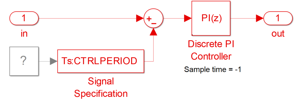
In most cases, inherited sample time (-1) ensures that the whole discretized control is executed at the proper rate. The illustration below shows a discrete PI controller whose sample time is -1 and the sample time is correctly propagated from outside the system:
In some cases, a certain block can enforce a wrong sample time, as in the example below, where the step block is continuous (its default sample time) and propagates the wrong sample time to the PI controller (in this case, this even results in an error, since the discrete PI cannot run at a continuous sample time):
To solve this, there are basically two options to force the sample time of a particular signal or block.
1) Set the sample time of the “faulty” block or the discrete block to CTRLPERIOD:
2) If the faulty block cannot be found or its sample time cannot be specified, use a Signal specification block with CTRLPERIOD as sample time


