Table of Contents
This article provides getting-started information for the B-Box Micro, highlighting the easy transition from computer simulation to laboratory testing. A practical “Hello World” example is developed, implementing a basic three-phase inverter operated in open loop.
Step-by-step guidance for programming and operating imperix controllers is also given in PN138. Getting-started instructions specific to the ACG SDK are also summarized in PN134.
Software for the B-Box Micro
To program its controllers, imperix provides two Software Development Kits (SDKs):
- The ACG SDK for graphical programming using Automated Code Generation (ACG) from Simulink or PLECS.
- The CPP SDK for development using C/C++ code.
This page focuses on using the ACG SDK with Simulink, which is the most common workflow with the B-Box micro. Most aspects are either identical or easier to apprehend with PLECS.
Detailed instructions for installing the SDK can be found in the installation guide. Essentially, the main steps can be summarized as:
- Installing (if not done already) the third-party tools along with the required code generation add-ons.
- Downloading and running the installer for the ACG SDK. Download links for either SDKs are available on https://imperix.com/downloads/. Compatible versions are indicated on the same page.
- For Simulink, a MEX compiler for C++ must be installed. Once this is done, the imperix installer handles the rest of the configuration.
- For PLECS, the path of the freshly installed Imperix_Controllers target support package (
C:\imperix\BB3_ACG_SDK\plecsby default) must be added to the PLECS Target support packages path in the PLECS preferences.
Developing control models
As the imperix knowledge base provides numerous examples, users can often start from a pre-existing example that is reasonably close to the intended application. It is also possible to start from scratch using the template model available in the ACG SDK’s installation folder.
Imperix control files are structured into two distinct subsystems: the Controller and the Plant.
- The Controller subsystem contains the control algorithms, implemented using any standard Simulink block that supports code generation, as well as blocks from the imperix Control library. The same subsystem can be used for both offline simulation and automated code generation.
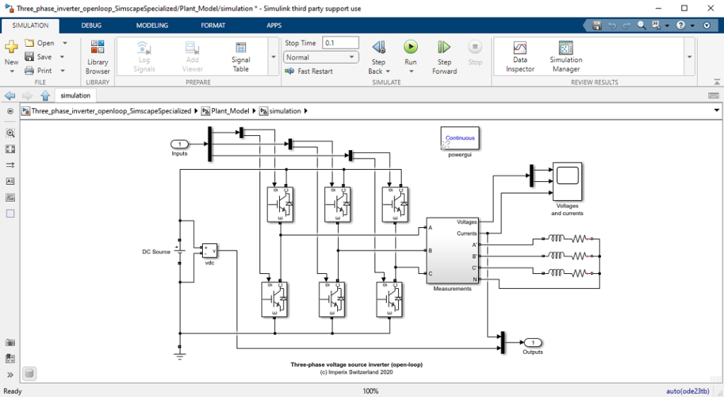
- The Plant subsystem contains a simulation model of the controlled system (plant), typically implemented with Simscape Electrical components or SPS blocks (in Simulink) or PLECS circuits (in PLECS), along with blocks from the Power library that model imperix power products. The Plant subsystem is solely used during offline simulation. It is therefore optional, but highly recommended.

Further explanations on the available libraries, how imperix models are typically built, and how hardware-specific aspects are modeled are provided in the Getting started guide for the ACG SDK. Additionally, specifics for each software package, notably regarding control discretization, are provided in PN135 for Simulink and PN137 for PLECS.
Generating runtime code
The same Simulink/PLECS model can be used for both simulation and code generation. To build the code, press Ctrl+B in Simulink (ensuring that the CONFIG block is set to Automated Code Generation) or Ctrl+Alt+B in PLECS. The software automatically generates the code, compiles it, creates an executable, and opens Cockpit.
– Licenses are usually pre-loaded on the controllers.
– All B-Box micro units require a license.
– The software can be installed on an unlimited number of computers.
More details on the licensing of imperix software are provided in imperix licensing.
Programming the B-Box Micro
Connecting the B-Box Micro to the host PC
An Ethernet connection must first be established between the computer and the B-Box Micro. This can be made either over an existing network or using a point-to-point connection. In both cases, a dynamic IP address is assigned automatically, and no specific configuration is required. Nonetheless, if required, further information on this process is given in PN138.

Loading and launching the code with Cockpit
After the code is generated in Simulink or PLECS, Cockpit opens automatically and prompts to create a new project. Projects associate a model with a target, i.e., the controller that receives the corresponding code. To associate a project with a target, click the Link Target button in the left pane of Cockpit. This displays the list of available targets, from which the desired controller can be selected.
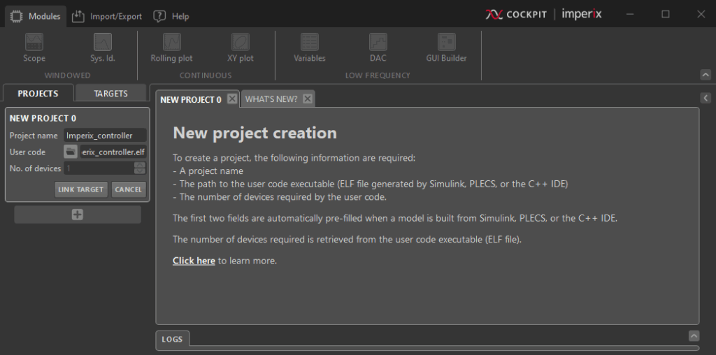
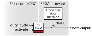
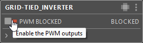
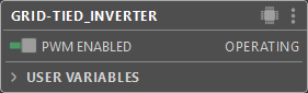
One the connection is established with the target, the code is automatically transferred and launched. However, PWM signals are not physically generated until the operator explicitly enables them. Enabling or disabling the gating signals can be done in Cockpit using the dedicated button (see images below). This effectively serves as an allow/block switch that determines when the converter is actually switching. More information about the corresponding operating states is provided in PN261.
Configuring the analog inputs and safety limits
Hardware configuration
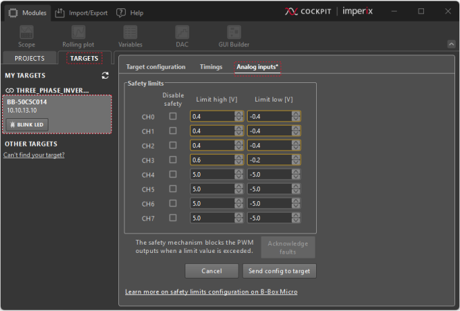
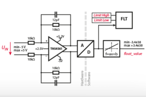
Unlike the B-Box 3 and B-Box 4 controllers, the B-Box Micro doesn’t require hardware configuration of its analog inputs, simply because they are not programmable. Nonetheless, each analog input has two FPGA-based comparators that serve as protection thresholds, which can be configured directly from Cockpit in the Analog input tab of the Target view. More details are presented in PN106. Also, a numerical example is given in the hands-on example below.
Software configuration
When setting up the ADC blocks in Simulink or PLECS, the following parameters must also be configured:
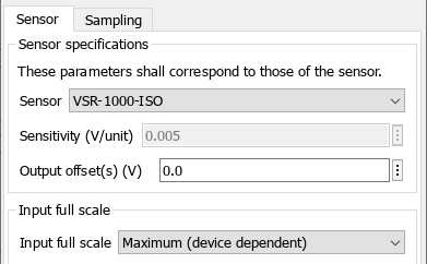
- Sensor: Selecting a sensor from the drop-down list automatically configures its sensitivity. For third-party sensors, the sensitivity must be manually entered in the Sensitivity parameter.
- Input full scale: This must remain set to Maximum. Because the B-Box Micro has a fixed input full-scale of ±5V, any different setting will be ignored and will generate a warning message in the log.
Acknowledging faults
If an overvalue occurs during operation, all PWM outputs are immediately blocked, and the core state is switched to FAULT. More information about the different fault sources is provided in PN261.
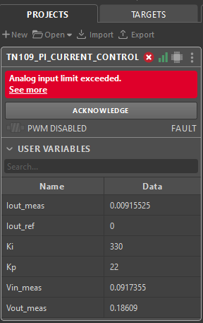
When this happens, an error message is displayed in Cockpit. Information about the origin of the fault can be found in the log messages. However, operation cannot be resumed until the fault is acknowledged by clicking the appropriate button (see image above).
Real-time control and monitoring using Cockpit
Cockpit provides a view where users can drag and drop modules to monitor and modify user-defined variables. If needed, related documentation is available in the dedicated user manual.
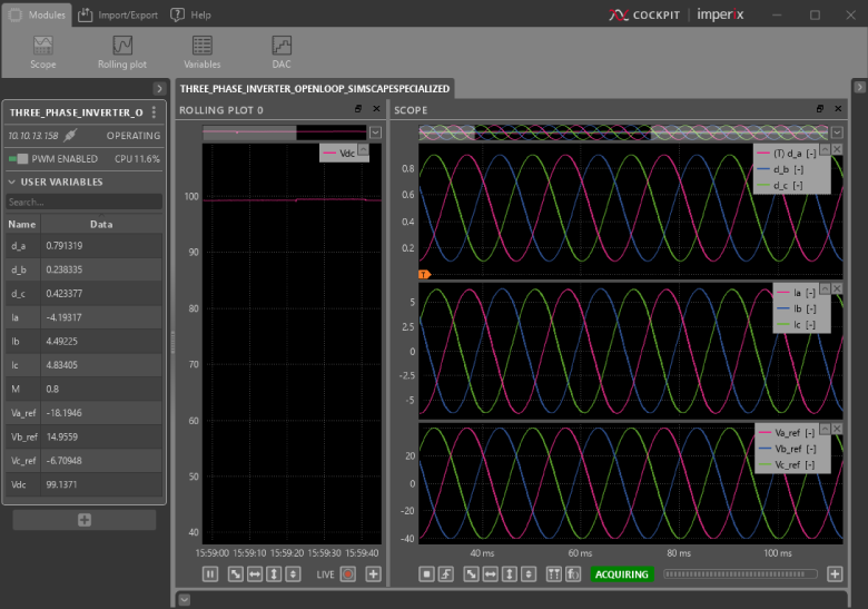
“Hello World” example
The illustration shows the use case example in which the B-Box Micro controls a three-phase inverter.
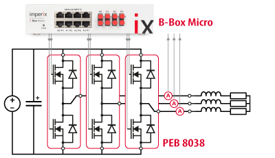
Open-loop control of a three-phase inverter
Hardware setup
This setup can be implemented with the imperix Starter kit. Some additional material, listed below, is however required to test the system before operating the complete converter.
- Laboratory DC power supply
- 3x power resistors
- 3x 2.5mH inductor
During the experiment, the inverter is connected to a three-phase RL load under the following conditions:
- DC-bus voltage: 100 V
- Control frequency: 20 kHz
- Sampling phase: 0.5 (middle of the switching period)
- Load resistance: 6 Ω
- Load inductance: 2.5 mH
Simulink model
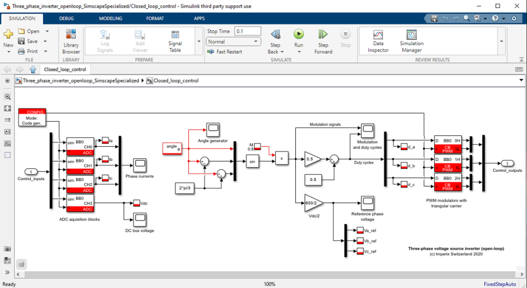
The Simulink model is available for download below. It implements a basic open-loop control for the three-phase inverter. To illustrate data monitoring from the B-Box Micro, the DC-bus voltage and the phase currents are measured and logged using Probe blocks.
Configuration of the safety limits
Assuming the load current is measured using the embedded current sensors of PEB8038 modules (offering a sensitivity of 50.0 mV/A), the Limit high and Limit low values can be computed as follows. The same approach applies to the DC voltage sensor.
- Current sensors (CH0, CH1, CH2)
- Maximum acceptable instantaneous current: ±8 A
- Corresponding sensor output: ±8 A x 50.0 mV/A = 400 mV
- Limit high: +0.4 V and limit low: -0.4 V
- Voltage sensor (CH3)
- Maximum acceptable DC voltage: 120 V
- Corresponding sensor output: 120 V x 4.99 mV/V ≈ 600 mV
- Limit high: +0.6 V and limit low: -0.2 V
Where to go next?
Various control techniques can be easily implemented and tested with the starter kit:
- PI control:
- Phase detectors:
- Modulation techniques:
- Advanced control techniques:
Thanks to the plug-and-play modules, many different applications can be addressed quickly:
 By Benedikt Borter • February 6, 2024 • PN106
 By Julien Orsinger • September 20, 2022 • PN138