Table of Contents
HDL Coder is a MATLAB add-on that can generate VHDL and Verilog code from MATLAB functions or Simulink models. This approach can greatly accelerate rapid prototyping as the design is performed from a higher level of abstraction. The second benefit is the possibility of simulating the FPGA logic directly from within Simulink.
A typical use case for HDL Coder is the implementation of a custom PWM modulator for the B-Box RCP power converter controller.
Intended use and alternatives to HDL Coder
An alternative to HDL Coder is System Generator, another Simulink add-on that works very similarly. The main difference between System Generator and HDL Coder is that System Generator targets exclusively Xilinx devices. As such, it generates pre-packaged core IPs that can easily be imported into Vivado. Moreover, System Generator is bundled with Model Composer, another FPGA development blockset that provides additional features that HDL Coder does not have.
Compared to high-level synthesis tools such as Model Composer (Simulink) and Vitis HLS (C++), System Generator and HDL Coder are “lower-level” design tools intended for architecture-level designs, down to the flip-flop register. MATLAB HDL Coder allows finer control over the resulting HDL code and is more adapted for peripheral designs (e.g. PWM modulator or SPI communication controller). Unlike Model Composer and Vitis HLS, System Generator does not support AXI4-Stream interfaces.
Licensing and installation of MATLAB HDL Coder
HDL Coder is a paid add-on for MATLAB, which also required the Fixed-Point Designer add-on, as well as the MATLAB Coder add-on.
Installing HDL Coder is straightforward: open a MATLAB session, go to the HOME tab and click on Add-Ons. Search for HDL Coder and hit install. The same process applies to Fixed-Point Designer and MATLAB Coder.
After the installation has finished, the HDL Coder library is available in the Simulink libraries. The command help hdlcoder may be used in the Command Window.
The hdlsetuptoolpath command must be entered in the MATLAB Command Window to setup the FPGA synthesis software. The path must be edited to match the installed Vivado version.
hdlsetuptoolpath('ToolName', 'Xilinx Vivado', 'ToolPath', 'C:\Xilinx\Vivado\20xx.x\bin\vivado.bat');Code language: Matlab (matlab)
Typical MATLAB HDL Coder workflow
This section broadly outlines the main steps required to generate VHDL or Verilog sources using MATLAB HDL Coder. For more detailed information the user should refer to the official documentation of which some are listed below:
Implementing a design using HDL Coder
The screenshot below shows an example of a MATLAB HDL Coder design taken from the custom FPGA PWM modulator page. This example will be used as a support to illustrate the key points of the MATLAB HDL Coder workflow. The sources are available in the zip below.
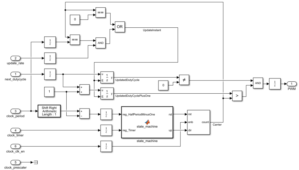
The user creates the design using HDL Coder blocks (available in the Simulink library browser) as illustrated above. The logic must be placed within a subsystem.
The input and output types are set as follows:
- i_nextDutyCycle, CLOCK_period, CLOCK_prescaler : 16-bit unsigned integer (Data type: uint16)
- CLOCK_clk_en, i_UpdateRate: 1-bit (Data type: boolean)
In HDL Coder, there is no model for the clock signal in FPGA. Instead, the sample period of the Simulink signals represents the FPGA clock signal period. In the FPGA PWM example, the clk_250_mhz output is used, which corresponds to a period of 4 ns.
Testing a design in simulation
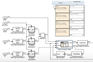
An HDL design can be validated using a test bench that uses standard Simulink blocks. Below is shown an example of a testbench, which is further documented in the FPGA-based PWM modulator example.
Generating RTL code using MATLAB HDL Coder
- Go to Apps and click on HDL Coder.
- Click on Workflow Advisor.

- In the pop-up window, select
- Generic ASIC/FPGA as target workflow,
- Xilinx Vivado as synthesis tool,
- Zynq xc7z030fbg676-3 as device.
- Set a correct project folder.
- Click on Run This Task.

- Set the target frequency to 250MHz.

- Run the rest of the tasks until 3.1.3 Set Advanced Options. There, set Reset asserted level to Active-low.

- Run the rest of the tasks, until 3.2. Generate RTL Code and Testbench finishes.
Do not run synthesis now, since we use MATLAB HDL Coder only to generate the RTL sources. The synthesis will be performed by Vivado.

HDL Code Generation -> Global Settings -> Ports -> Minimize clock enables (check this box).
Adding the module to a Vivado project
Unlike System Generator, MATLAB HDL Coder does not generate a Vivado IP directly. Instead, the generated RTL sources must be added to Vivado.
- In Vivado, right-click on the Design Sources and select Add Sources
- Browse into the generated folders and select the source files
- Give Vivado some time to update its sources hierarchy
- Finally, the module can be added to the block design:
- by doing a right-click and selecting Add Module…
- or by directly drag-and-dropping the design source
A step-by-step example explaining how to integrate the PWM modulator IP in a Vivado project is available on the FPGA PWM modulator page.


