Table of Contents
Xilinx System Generator for DSP (SysGen) is a MATLAB Simulink add-on that enables the development of architecture-level FPGA designs using graphical blocks programming. Users can validate their designs through simulation in Simulink and the design can be packaged into a Vivado IP and easily imported into a Vivado project.
Alternatives to Xilinx System Generator
An alternative to System Generator is MATLAB’s HDL Coder, another MATLAB Simulink add-on that works very similarly. The main difference between System Generator and HDL Coder is that System Generator targets exclusively Xilinx FPGA devices. As such, it generates pre-packaged core IPs that can easily be imported in Vivado. Moreover, System Generator is bundled with Model Composer, another FPGA development blockset that provides additional features that HDL Coder does not have.
What is the difference between System Generator and Model Composer?
Compared to high-level synthesis tools such as Xilinx Model Composer, System Generator is a “lower-level” design tool intended for architecture-level FPGA designs, down to the flip-flop register. System Generator allows for finer control over the resulting HDL code and is more adapted for FPGA peripheral designs such as PWM modulators or SPI controllers. Unlike Model Composer and Vitis HLS, System Generator does not support AXI4-Stream interfaces.
Downloading and installing Xilinx System Generator
System Generator, along with Model Composer is part of the Xilinx Add-on for MATLAB & Simulink which can be bought as an add-on license to Vivado or Vitis. At the time of writing this page, the price is set at $500 for a node-locked license and $700 for a floating license (a free 90 days license is available).
To install the Xilinx Add-on for MATLAB & Simulink, an option must be selected during the installation of Xilinx Vivado System Edition. If Vivado is already installed, the Vivado Add Design Tools program should be used to install the add-on.
More information on the Xilinx Add-on for MATLAB & Simulink is available on this Xilinx page.
Installation instructions are available on the Xilinx Blockset for Simulink page.
Typical workflow
This section broadly outlines the main steps required to generate a Vivado IP using System Generator. For more detailed information, the user should refer to the official documentation of which some are listed below:
- Vivado Design Suite User Guide: Model-Based DSP Design Using System Generator (xilinx.com)
- Vivado Design Suite Tutorial: Model-Based DSP Design Using System Generator (xilinx.com)
How to launch System Generator?
If Xilinx Add-on for MATLAB & Simulink has been successfully installed, a “Model Composer and System Generator” shortcut should have been created on the desktop. This program will open a new MATLAB session and load the Xilinx System Generator library for Simulink.
Implement a design using System Generator
The image below shows an example of a System Generator design taken from the custom FPGA PWM modulator page. This example will be used as support to illustrate the key points of the System Generator workflow. The sources are available in the zip below.
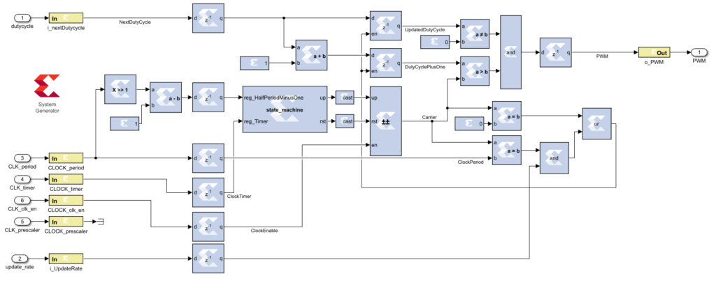
The design should use System Generator blocks (available in the Simulink library browser, under Xilinx Toolbox -> HDL, or more recently under AMD Toolbox -> HDL) and the following points should be observed:
- The logic has to be placed in a subsystem
- The Gateway in and Gateway out blocks have to be used to represent the input/output ports of the generated IP
- Between the Gateway blocks, only blocks from the Xilinx Toolbox/HDL library should be used
- A System Generator block has to be added as a control panel for simulation and IP generation.
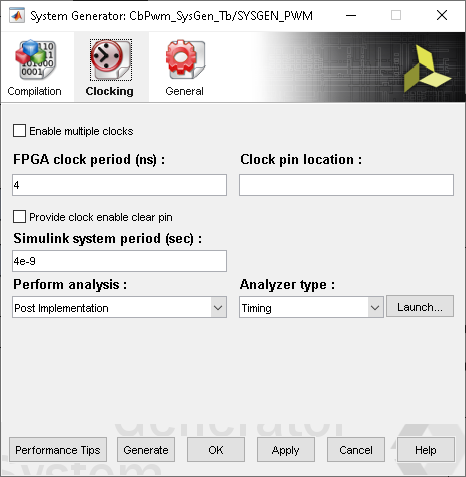
The sample period must be set to match the clock frequency that will be used in the FPGA. In the imperix controller FPGA design, the clk_250_mhz output is used most of the time. It corresponds to a period of 4 ns.
The following configuration is used:
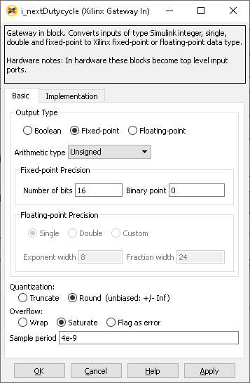
- Sampled period of all Gateway In blocks is set to 4e-9
- Simulink system period (sec) under the Clocking tab of the System Generator block is set to 4e-9
- FPGA clock period (ns) under the Clocking tab of the System Generator block is set to 4
The input and output types are set as follows:
- i_nextDutyCycle, CLOCK_period, CLOCK_prescaler : 16-bit unsigned integer (Fixed-point, Unsigned, Number of bits: 16, Binary point: 0)
- CLOCK_clk_en, i_UpdateRate: 1-bit (Boolean)
Testing the design in simulation
A Xilinx System Generator design can be validated by building a test bench that uses standard Simulink blocks. Below is shown an example of a testbench, which is further documented in the FPGA PWM modulator example.

Generating a Vivado IP Core using System Generator
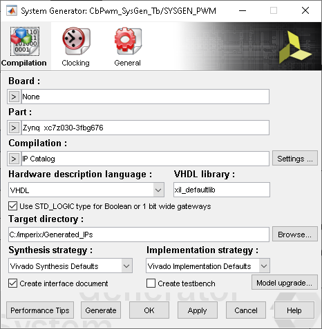
The Vivado IP generation is launched from the System Generator block. The user defines a target directory and then clicks on Generate, as shown below. The compilation and generation take approximately 5 minutes for the provided FPGA PWM modulator example.
To use this IP in a Vivado project, the user has to:
- Open the IP Catalog
- Right-click and select Add repository…
- Select the path to the generated IP (for instance
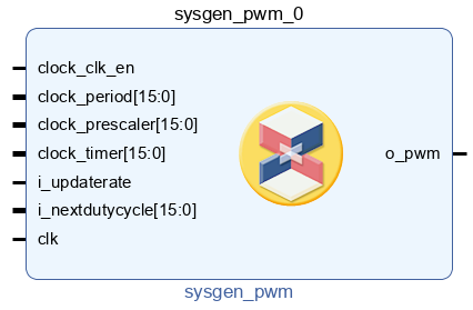
C:\KB\PN161\Generated\ip) - The generated IP (shown below) can then be added to a block design like any other IP
A step-by-step example explaining how to integrate the PWM modulator IP in a Vivado project is available on the FPGA PWM modulator example page.


