Table of Contents
This document provides guidance for first-time users on the essential procedures for deploying code to imperix controllers and connecting to the equipment. It is applicable to all variants of programmable controllers, including B-Box 4, B-Box 3 (RCP), B-Box 3 Micro, B-Board 3 (PRO), and TPI8032. Among other aspects, it notably addresses:
- Code generation: how to generate and compile code using Simulink, PLECS, or the imperix IDE.
- Connectivity: how to establish the PC ↔︎ Controller connection via Ethernet.
- Monitoring basics: the fundamentals of remote monitoring and debugging using Cockpit.
Before following this guide, readers who work with Simulink or PLECS are advised to consult the articles on the ACG workflow shown in the table below. A series of video tutorials is also available with similar content. Readers who develop their code in C/C++ should consult PN146 for instructions about the CPP SDK.
| Step | Documentation | Videos | |
|---|---|---|---|
| 1. Software installation | Installation guide for the ACG SDK PN133 | N/A | |
| 2. Getting started | Getting started with the ACG SDK PN134 | Create the model Video 1 | |
| 3. Running simulations | Simulation essentials with Simulink PN135 | Simulation essentials with PLECS PN137 | Simulate it Video 2 |
| 4. Device programming | Programming and operating imperix controllers PN138 | Generate code Video 3 | |
| 5. Monitoring | Cockpit user guide PN300 | ||
Programming workflows
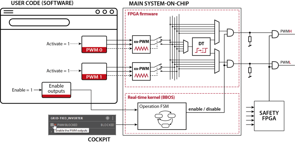
Imperix controllers utilize a CPU+FPGA architecture to execute control algorithms. Typically, the control task (user code) runs on the CPU, while low-level, time-critical functions (such as PWM modulation and safety) are handled by the FPGA. More information about the devices' architecture is available in PN253.
Thanks to their similar architecture, all imperix controllers benefit from an identical development workflow, consisting of the following two phases:
A) Control code development and offline simulation: With Simulink or PLECS, this phase takes place entirely within the simulation software on the PC. It includes the implementation of the control algorithms themselves, as well as the optional - but highly recommended - modeling of the plant and validation of the algorithms using offline simulations. With the imperix IDE, only C/C++ code can be implemented. Offline simulation is not supported. This phase is mainly covered by the dedicated user guides: general getting-started instructions in PN134, and software-specific instructions in PN135 (Simulink) and PN137 (PLECS).
B) Code generation and device programming: With Simulink or PLECS, this phase also takes place within the simulation software, thanks to automated code generation. Subsequently, once the runtime executable code is generated, its deployment and all interactions with the hardware occur via imperix's dedicated software, Cockpit. This second phase is the main object of this article.
For the first step (A), imperix supports three possible development environments, summarized below. For the second step B), all actions rely on Cockpit, independently of the chosen development environment.
| Environment | Language | Offline simulation | Required SDK | User guide |
| Simulink | Graphical 1) | Yes 2) | ACG SDK 3) | ACG user guide |
| PLECS | Graphical 4) | Yes | ACG SDK 3) | ACG user guide |
| Imperix IDE | C/C++ | No | CPP SDK 5) | CPP user guide |
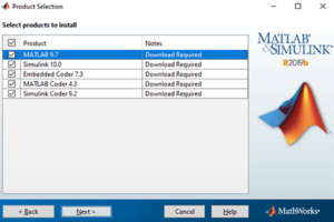
1) requires Matlab Simulink, Matlab Coder, Simulink Coder, and Embedded Coder
2) requires Simscape Electrical or PLECS Blockset for Simulink
3) requires specific license issued by imperix (more details in Licensing)
4) requires PLECS and PLECS Coder
5) requires specific license issued by imperix (more details in Licensing)
Phase A) - Developing and generating a real-time control code
Using Simulink or PLECS
Code development
As introduced in PN134, when developing control code on Simulink or PLECS with ACG SDK, the model is usually organized with two main subsystems, each serving a distinct purpose in the development workflow:
- Plant subsystem: Used only in Simulation mode, this subsystem enables offline validation and tuning of the control algorithm. It uses blocks from the Power library and Simscape Electrical / PLECS blocks to model the hardware dynamics of imperix power products. In Automated Code Generation mode, it is ignored.
- Controller subsystem: Used for both Simulation and Automated Code Generation. It contains the core control implementation along with target-specific peripheral blocks (such as ADC and PWM) from the Control library for direct deployment to the hardware.
Important guidelines and best practices for effective use of Simulation mode are provided in PN135 (Simulink) and PN137 (PLECS).
Code generation
Once implemented and tested, the Simulink or PLECS model must be translated into code and compiled into an executable before it can be deployed onto the target. This process is handled automatically by Simulink or PLECS, thanks to the scripts and configuration files installed by the ACG SDK. From the user's perspective, all these tasks are carried out in one click using the following procedure:
In Simulink:
- Select “Automated Code Generation” in the CONFIG block of the model.
- Select the right generation of the controller. The B-Box 4 is "Gen. 4". Other controllers are "Gen. 3". This information is required by the compiler to account for hardware-specific instructions.
- Build the model by clicking the “Build” button (or with the shortcut Ctrl+B).
If the Build button is not shown, make sure that Simulink Coder and Embedded Coder are installed, and open the Embedded Coder app in the APPS tab. The Build button should appear in a new C CODE tab.
In PLECS:
- Open the Coder > Coder option window (Ctrl+alt+B).
- Select the subsystem containing the control implementation in the left column.
- In the Target tab, select the target generation corresponding to your controller. The B-Box 4 is "Gen. 4". Other controllers are "Gen. 3". This information is required by the compiler to account for hardware-specific instructions.
- Click the "Build" button to start the building process.
At the end of a successful build, Cockpit automatically launches and creates a new project with a pre-filled project name. Now, to deploy the code to the target, a connection must be established, as detailed below (phase B).
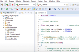
Using the imperix IDE for C/C++
This workflow uses the imperix IDE, an Integrated Development Environment (IDE) built on the Eclipse platform. Users are required to implement their control algorithm directly in C or C++. The workflow relies on a provided library of peripheral routines (effectively hardware drivers) to interface with each hardware resource. A simple API is also provided for interfacing the application-level code with kernel functions.
To build the code and generate the runtime executable, select the current project in the project explorer, then click the “Run” icon (green play button). Specific getting-started instructions are provided in PN148.
Phase B) - Code flashing and monitoring in Cockpit
Once the code is generated, it is uploaded to the controller (hereafter called the target) via Cockpit, which opens automatically at the end of the build process.
Connecting the target to the host PC
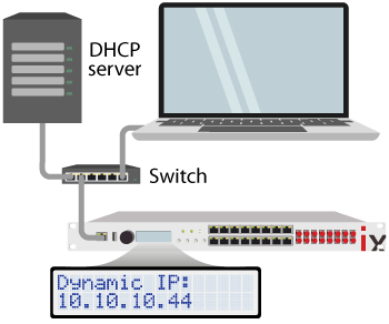
First, an Ethernet connection must be established between the host computer and the target(s). Two scenarios can be implemented:
- The target is connected to a local Ethernet network. In this case, an IP address is generally automatically attributed to the target by a server or router (over DHCP).
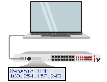
- A point-to-point link is established between the target and the host computer using a single Ethernet cable. In this case, the IP address is automatically assigned from the 169.254.x.x range.
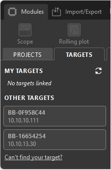
In Cockpit, no specific configuration is required. Connected targets are normally auto-detected and appear in the left bar of the Target perspective, as shown on the right.
For the computer to communicate with the target, IP communication must be possible, which means both devices must belong to the same network.
If the target is connected to a local network the computer is already connected to, it will usually receive a compatible IP address automatically. In this case, Cockpit should automatically find the target on the network and display it in the target list. If not, its IP address can be manually added by clicking the Can't find your target? link.
If this address is unknown, it can be easily found on the B-Box 3 and 4 using the front panel. However, with a TPI, B-Box Micro, or B-Board PRO, such a display does not exist. Manually configuring the computer's IP address within the same range as the target's backup static IP address may be the only recourse (see PN144).

In this case, manually configuring the computer's IP address may be required (see PN144).
These ports must not be blocked by a firewall.
In the case of a direct point-to-point connection (e.g., using a USB-to-Ethernet dongle adapter), both the computer and the target should automatically assign an IP address from the 169.254.x.x range. This process is known as Automatic Private IP Addressing (APIPA).
In this case, Cockpit should automatically find the target on the network and display it in the target list. If not, its IP address can be manually added by clicking the Can't find your target? link.
Flashing and launching the code
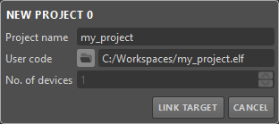
At the end of a successful build, Cockpit automatically launches and creates a new project with a pre-filled project name and path. From there, only a few steps are required to load the code to the target and launch it:
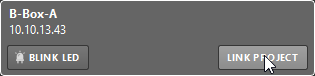
- Using the Cockpit left bar, click on "Link target" and choose the desired target (see images below).
- Once the project is linked to a target, the code is immediately uploaded to that target and launched.
- If the code is re-generated from the same location (i.e., the model is rebuilt), Cockpit simply loads the new version of the code and restarts it.
More information on managing projects in Cockpit is given in the Cockpit user guide.
Enabling PWM outputs
Once the code is deployed on the target, it is automatically launched and runs continuously. However, the PWM signals are not produced at the device's physical outputs unless explicitly enabled by the operator. Enabling or disabling the gating signals is done in Cockpit using the dedicated button (project-related, left pane). This effectively serves as an allow/block switch that determines when the converter is actually switching.
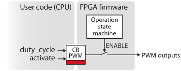
- enable/disable is a global setting related to protection and manual start/stop actions on switching.
- activate/deactivate selects which channel will actually produce an output once enabled. This is controlled by the user code, typically to selectively turn different parts of a power converter on or off.
Understanding the CORE operating states
Imperix controllers have three possible states and conform to the state diagram below.
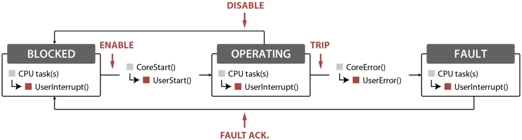
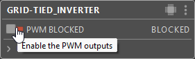
- BLOCKED: The CPU tasks are running, but all PWM outputs are blocked (ready to be enabled).
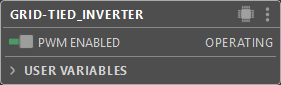
- OPERATING: The PWM outputs are enabled, and the system is operating without errors.
- FAULT: An error occurred, and the system is waiting for acknowledgment. The PWMs are blocked.
The controller goes into OPERATING state when the PWM outputs are enabled, and goes back to BLOCKED state when disabled.
In case of error (e.g. due to an overcurrent detection in the power setup), the controller immediately goes into FAULT state, which immediately disables the PWM outputs. The source of the fault is described in Cockpit, either in the red banner located in the "Project pane“ (see image below) or in the "Log module". The return to the OPERATING mode is only allowed once the fault is cleared and acknowledged by the user.
If anything goes wrong during converter operation, such as an overcurrent being detected, PWM outputs are immediately blocked by software-independent protections. Information about the fault source is provided in Cockpit's Log module and on the front panel (B-Boxes 3 and 4). Users must then acknowledge that a hardware, software, or user fault has occurred before operation can be resumed. Until then, the controller is frozen in the so-called FAULT state.
Controllers can reach the FAULT state for various reasons. The most common ones are listed in the table below. Any fault immediately switches off the PWM outputs, stopping the converter's operation.
| Cause | Type | Reason(s) |
|---|---|---|
| Configuration | Software | Misconfiguration, such as a physical resource being used multiple times (e.g. an analog input channel can't be used twice). |
| Overrun | Software | Excessive interrupt frequency considering the code complexity. |
| Code crash | Software | Can be a CPU or FPGA watchdog expiration, a C exception, etc... |
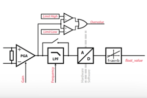
| Overvalue | Hardware | The configured threshold on an analog input has been exceeded. |
| Interlock | Hardware | A fault is triggered by an external device connected to the interlock connector (electrical or optical). |
| Fault line | Hardware | One of the fault inputs (FLT) is pulled high. |
| User code | User | An error has been intentionally thrown from within the user code. |
More information about the operating states that govern imperix controllers is provided in PN261. Further details on their hardware protection mechanisms are provided in PN263.
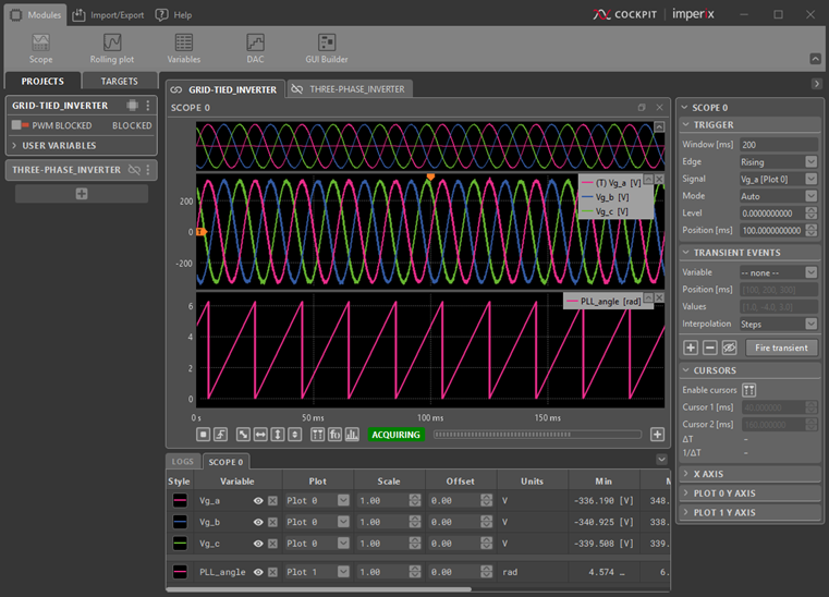
Monitoring the controller in real-time using Cockpit
Cockpit offers different visualization modules that can be fed with real-time data. In fact, any signal connected to a Probe or Tunable parameter block can be monitored in Cockpit. The most useful modules include:
- Scope module to display variables at the control rate, or oversampled data (B-Box 4 only).
- Transient generator to apply reference steps and ramps.
- Spectral Analyzer to analyze data in the frequency domain.
- GUI Builder module to create custom dashboards for interacting with the controller.
Cockpit's user manual provides more details on the software's capabilities.
Using the protection mechanisms
Imperix controllers feature configurable hardware protections that operate independently from the rest of the system. Notably, overvoltage thresholds can be easily configured for each analog input channel. These provide vital protection for the power stage and surrounding equipment.
Details on the working principle of these protections are provided in PN263. Practical information on how to configure them is provided in the device-specific documentation listed in the table below.
| Controller | Configurable through | Device-specific documentation |
|---|---|---|
| B-Box 4 | - Device front-panel (LCD+button) - Cockpit Analog I/O tab | PN252 |
| B-Box 3 (RCP) | - Device front-panel (LCD+button) | PN105 |
| B-Board 3 (PRO) | N/A | N/A |
| B-Box 3 micro | - Cockpit Analog I/O tab | PN106 |
| TPI8032 | N/A | PN190 |
Where to go from here?
Get started with specific controllers
Get inspired by numerous code examples
Build power converter setups
Learn how to program the FPGA of the controller