
Table of Contents
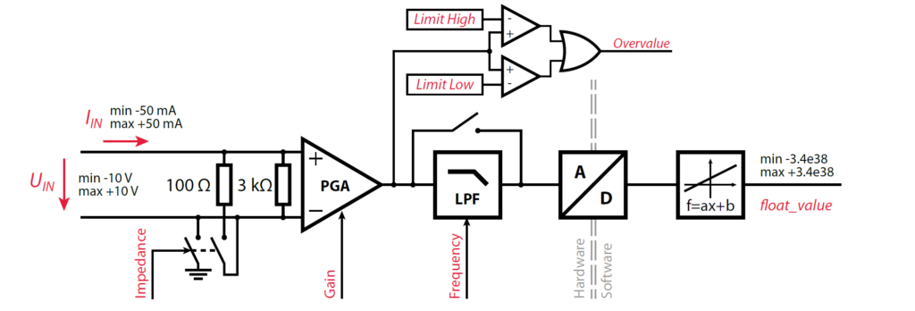
The B-Box 3 (RCP) has 16 identical analog input channels. The equivalent schematic of the data acquisition chain is shown below. Each channel consists of two parts:
- A hardware part, which contains a configurable input impedance, a programmable gain amplifier (PGA), a low-pass filter (LPF), and the analog-to-digital converter (ADC).
- A firmware and software part, which is responsible for transferring all data to the CPU and transforming the converted value into a meaningful quantity, considering the sensitivity of the whole chain, from the sensor to the converted value.
Front-end configuration (hardware)

The LCD screen and rotary push buttons allow editing of all configuration parameters of the analog front-end. To access the related menu:
- Push once, select
ANALOG INPUTSand confirm (push again). - Select the desired input channel and confirm.
The following options are available:
| Menu | Available values | Comment |
|---|---|---|
| Input impedance | Low, High | Low = 100Ω / High = 3kΩ |
| Gain | 1x, 2x, 4x, 8x | This is equivalent to setting the input scale to ±10V, ±5.0V, ±2.5V and ±1.25V. |
| Filter | 0.5kHz, 1kHz, 1.6kHz, 2.5kHz, 4kHz, 6.4kHz, 8kHz, 10kHz, 16kHz, 20kHz, 32kHz, 40kHz | More information on the corresponding group delay can be found in the datasheet. |
| Limit high | -10V to +10V | Increments of 0.1V. Precision is approx ±0.2V. |
| Limit low | -10V to +10V | Increments of 0.1V. Precision is approx ±0.2V. |
| Disable safety | Yes / No | Can be used to disregard the protection thresholds. In this case, the green LED indicator switches off on the corresponding input channel. |
Configuring the hardware safety limits
The analog front-end of the B-Box 3 provides hardware protection that halts operation if any analog input exceeds a configured limit, typically ensuring that the controlled power converter’s ratings are never exceeded. More information on the implementation and the operating principles of the hardware protections is given in PN263.
On B-Box 3, the reaction time of the protections cannot be configured. It is always ~1.6μs. Additionally, the bandwidth of the employed sensor may further limit this reaction time.
Numerical example
We consider here a sinusoidal current measured by a DIN50A sensor that should not exceed 20 A (RMS value). The sensor sensitivity is 99.0 mV/A, and a x2 gain is configured on that analog input channel. The Limit High and Limit Low values are computed as follows:
- Maximum acceptable instantaneous current: \(\pm 20\,\text{A}\times\sqrt{2}=\pm 28.28\,\text{A}\)
- Corresponding sensor output: \(\pm 28.28\,\text{A} \times 99\,\text{mV/A} = \pm 2.8\,\text{V}\)
- Limit High and Limit Low values: \(\pm 2.8\,\text{V}\times 2 = \pm 5.6\,\text{V}\)
Storing and restoring a configuration
The configuration of the front panel can be saved on a USB key, using the BACKUP CONFIG menu of the front panel. The configuration is automatically (and always!) stored in a file named “frontpanel0.bbox” on the USB key. In this way, the configuration can be saved for different applications.
The configuration can be restored by using the RESTORE CONFIG menu. The B-Box will search for files named “frontpanel#.bbox” in the imperix folder of the USB key, # being a number. The configuration file with the highest number is restored.
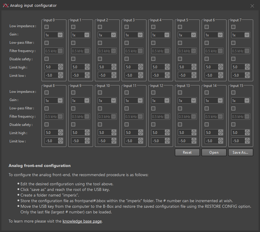
Reading and writing configuration files
The configuration file can be generated using Cockpit. To do so:
- On a computer, edit the desired configuration using Cockpit.
- Click “save as” and reach the root of the USB key.
- Create a folder named “imperix”.
- Store the configuration file as frontpanel#.bbox within the “imperix” folder. The # number can be incremented at wish.
- Move the USB key from the computer to the B-Box and restore the saved configuration file using the
RESTORE CONFIGoption. Only the last file (largest # number) can be loaded.
The front-end is physically independent of the main processing circuit by design. This guarantees superior reliability of the safety settings, which cannot be altered by software. For this reason, the configuration cannot be loaded automatically via Cockpit, and a USB key is required.
Software configuration
In addition to (and independently of) the hardware configuration of the analog front-end, the software configuration of the B-Box 3 must be implemented to reflect the corresponding parameters.
Simulink blockset
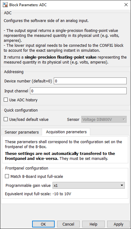
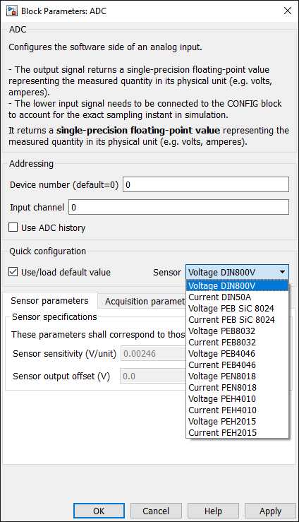
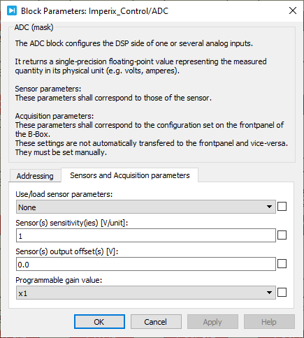
Each ADC block must be configured to account for the connected sensor as well as the front-end configuration. When imperix sensors are used, the associated parameters can be automatically loaded from a drop-down list.
PLECS blockset
The configuration in PLECS is similar to that in Simulink.

C/C++ configuration
The dedicated C/C++ routines are described in the corresponding software reference page. Each ADC channel must be configured during the initialization phase using:
void Adc_ConfigureInput(uint channel, float gain, float offset, uint bboxid=0);channelis the analog input channel number.gainandoffsetmust be configured given that the returned value during operation is computed as \(y=a x + b\), where \(a\) is the gain and \(b\) the offset.- bboxid is the ID of the addressed B-Box (optional parameter, useful in a multi-B-Box configuration only).
Numerical example:
This example considers the current sensor of a PEB8024 module. Its sensitivity is \(S=50.0\,[\text{mV/A}]\). As recommended in the datasheet, the front-end gain is selected as \(G=2\).
Considering that the ADC offers 16 bits over the ±10V input range, this results in a total sensitivity of \(\alpha = S\cdot G\cdot 32768/10=327.68\,[\text{bit/A}]\).
In this example, gain must therefore be equal to \(a=1/\alpha=3.052\,[\text{mA/bit}]\). The offset value can be adjusted empirically to cancel the measured value when no current is flowing through the sensor (static offset).
Subsequently, within each interrupt, the latest value can be retrieved using Adc_GetValue():
float Adc_GetValue(uint channel, uint bboxid=0);channelis the analog input channel number.bboxidis the ID of the addressed B-Box (optional parameter, useful in multi-B-Box configuration only).
 By Benedikt Borter • February 6, 2024 • PN106
 By Julien Orsinger • September 20, 2022 • PN138
 By Gabriel Fernandez • November 26, 2025 • TN181