Table of Contents
This article presents a Power Hardware-in-the-Loop (PHIL) application integrating imperix hardware with third-party simulators. In this example, the setup emulates a microgrid, and loads it with a physical three-phase resistive load. Necessary files to reproduce this example are provided for OPAL-RT, Plexim and Typhoon.
The proposed setup leverages the high-speed SFP communication link to exchange data between an imperix TPI inverter and the simulator. More information about the implementation of the related drivers can be found in SFP communication drivers.
For a more detailed overview of PHIL testing with imperix, please refer to TN183. Alternatively, TN185 presents a more advanced application, where a B-Box 4, power modules and a simulator emulate a Permanent Magnet Synchronous Machine to validate the control and hardware of a physical drive.
System description
The figure below illustrates the architecture of the proposed PHIL validation setup. A third-party simulator executes a microgrid model in real-time, computing the voltages at the connection point. These voltages are physically replicated by an imperix programmable inverter (TPI8032) onto the terminals of a three-phase resistive load.
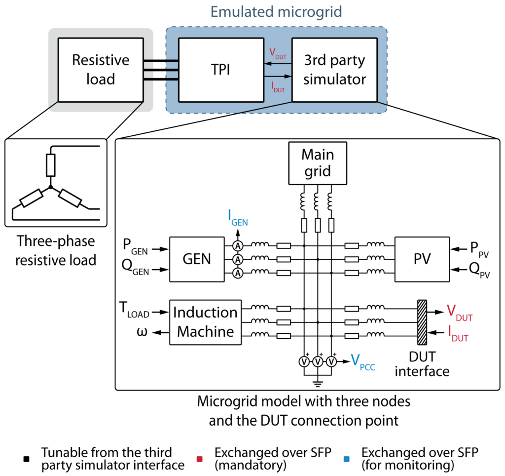
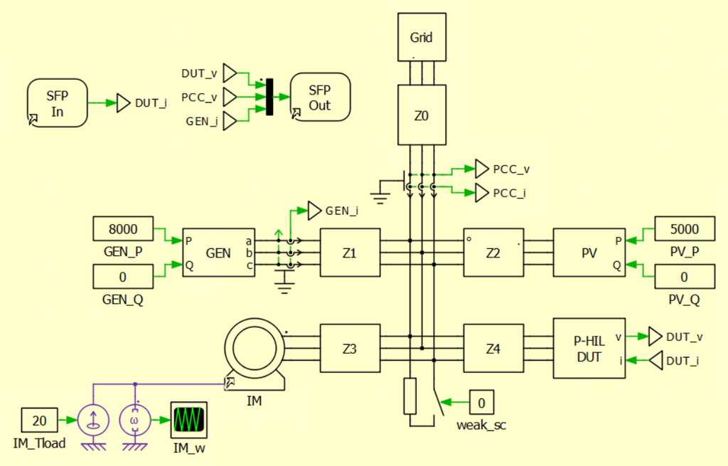
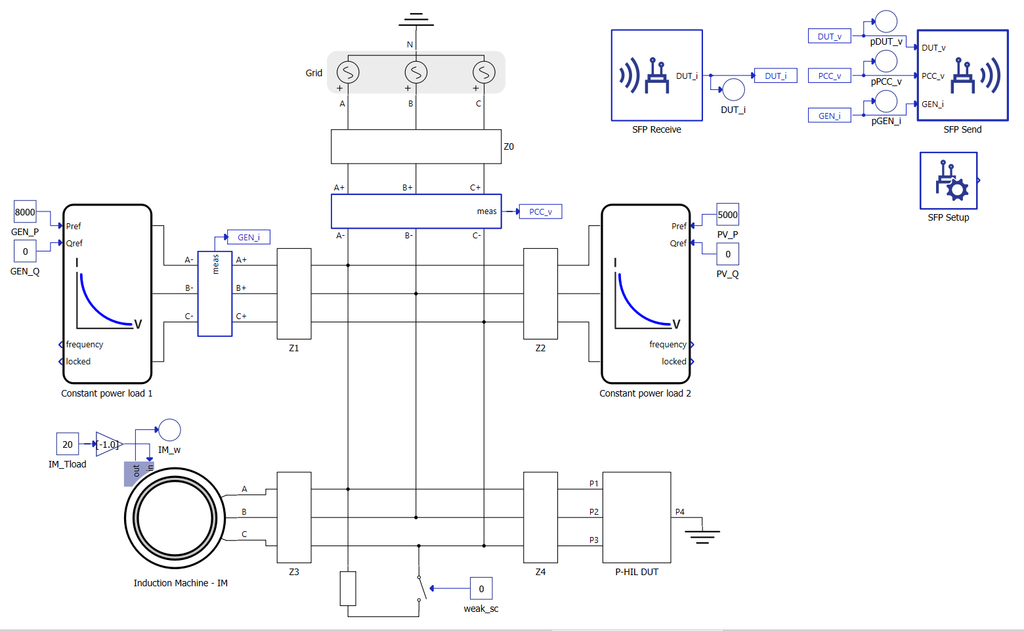
The simulated microgrid consists of a four-node network incorporating a generator (GEN) and photovoltaic system (PV) – both modeled as ideal power sources with adjustable active and reactive power setpoints – and an induction machine operating under variable torque (\(T_\text{LOAD}\)) and speed (\(\omega\)) conditions.
The DUT interface follows the Ideal Transformer Model: voltmeters extract the target voltages (\(V_\text{DUT}\)) to be generated by the TPI, while controlled current sources inject the measured physical currents (\(I_\text{DUT}\)) back into the simulation model to close the real-time loop. These quantities are exchanged with the TPI over the SFP connection, along with additional data from the simulation for visualization in Cockpit.
Downloads
This example relies on three software components:
- The power amplifier control model executed on the imperix TPI’s CPU.
- The vendor-specific bitstream with Aurora drivers to be loaded onto the imperix TPI’s FPGA.
- The vendor-specific microgrid simulation model to be loaded onto the third-party simulator.
The list of supported devices is available here.
Power amplifier control model
In order to follow the voltage references received from the simulator, the programmable inverter runs a voltage tracking algorithm. The model available below is directly adapted from the DQ control of TN168. Once built from PLECS, it must be loaded onto the TPI’s CPU via Cockpit.
Bitstream with Aurora drivers
In this example , the imperix programmable inverter and the simulator communicate over SFP, which requires a vendor-specific bitstream to be loaded onto the inverter’s FPGA. The bitstream contains Aurora drivers specifically designed for the targeted third-party vendor and must therefore be selected accordingly.
To generate the bitstream, download the bitstream generation scripts from the table below and follow the step-by-step bitstream generation procedure. For interested readers, the related pages are linked in the table below ; they provide explanations about the embedded drivers.
| Vendor | Bitstream generation scripts | Related page |
| OPAL-RT | aurora_ix_opalrt_gen_scripts.zip | Aurora link with OPAL-RT via SFP |
| Plexim | aurora_ix_plexim_gen_scripts.zip | Aurora link with Plexim via SFP |
| Typhoon | aurora_ix_typhoon_gen_scripts.zip | Aurora link with Typhoon via SFP |
Microgrid simulation files
The microgrid depicted in the system description has been implemented for each vendor. The corresponding files are available in the table below.
| Vendor | Microgrid model |
| OPAL-RT | phil_ugrid_ix_opalrt_rtlab.zip |
| Plexim | phil_ugrid_ix_plexim_rtbox.plecs |
| Typhoon | phil_ugrid_ix_typhoon_files.zip |
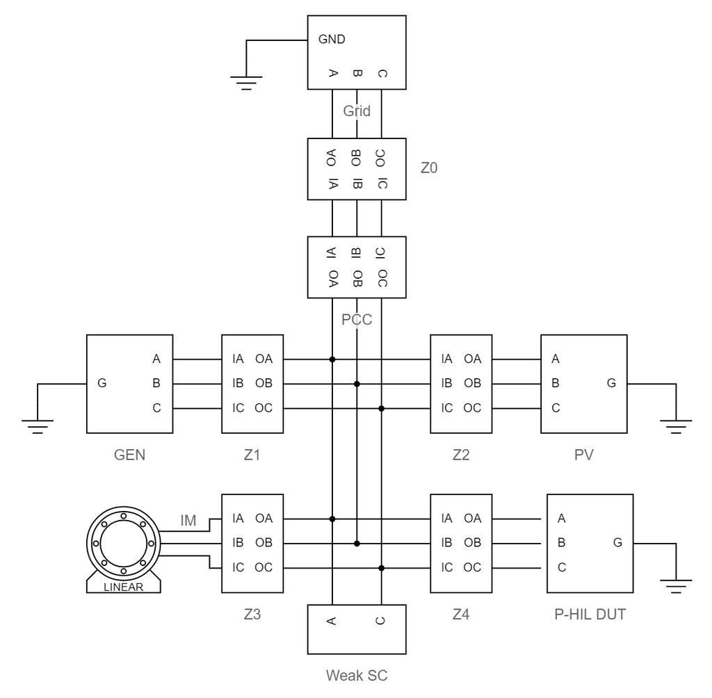
OPAL-RT Schematic Editor
Plexim PLECS environment
Typhoon Schematic Editor
Experimental validation
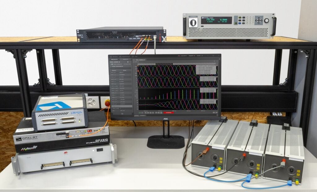
The lab setup is depicted below. As detailed in the system description, it consists of an imperix programmable inverter (TPI8032), a third-party simulator and a three-phase resistive load. An auxiliary DC source supplies power to the TPI. The figures in the next section have been generated using 87.5 Ω resistors.
The step-by-step setup procedure to reproduce the results presented in the next section is detailed in the expandable area below.
Results
This section presents the experimental results collected during laboratory validation. While these measurements were acquired using an RT-Box 1, equivalent results were obtained with an OPAL-RT OP4510 and a Typhoon HIL506.
The figures illustrate the programmable inverter’s perspective. The first plot compares the voltage references received from the simulator (DUT_V_ref) with the physical voltages applied on the load’s terminals (DUT_V), demonstrating the tracking performance of the TPI. Additionally, because the DUT behaves as a purely resistive load in this example, the measured currents (DUT_I) are in phase with the applied voltages.
Thanks to the high-speed SFP communication between the TPI and the simulator, additional simulation variables – such as the PCC voltages (PCC_V) and generator currents (GEN_I) – can be transmitted and monitored directly from Cockpit.
Generator setpoint increase
In the following figure, the active power of the emulated generator is linearly increased from 1 to 8 kW (reactive power remains at 0).
As expected, the amplitude of the generator’s currents (GEN_i) increases from 2.90 to 23.2 A and the PCC voltage slightly increases due to the line impedance between the PCC and the grid. Although not easily discernible on the figure, the DUT voltages and currents adjust accordingly.
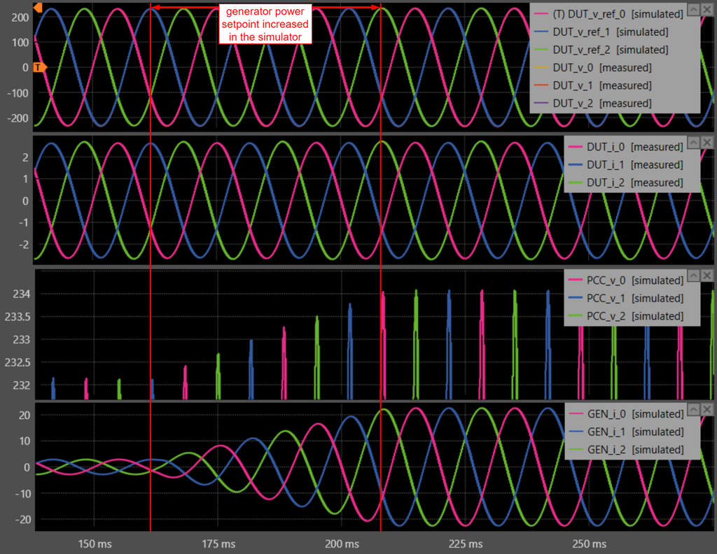
the emulated generator power (Cockpit software)
Grid phases weak short circuit
In the figure below, a weak short circuit with a fault impedance of 1 Ω is simulated between phases 1 and 3 at the PCC. As expected, this creates an immediate voltage drop on these two phases and a lasting voltage imbalance at the PCC.
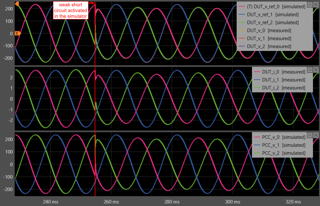
circuit between two grid phases (Cockpit software)
Going further
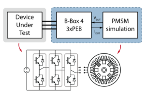
The PHIL PMSM example demonstrates a more advanced setup where a Permanent Magnet Synchronous Machine is emulated using a B-Box 4 and power modules to validate the control and hardware of a physical drive.
 By François Ledent • September 29, 2026 • TN185