

Table of Contents
Islanding occurs when a distributed energy resource continues to energize part of the network after that part has been disconnected from the main grid [1]. Grid codes such as IEEE 1547-2018 therefore require anti-islanding protection. Specifically, the inverter must detect the island and stop energizing within 2s [2]. The background of islanding detection is covered in TN173.
The General Electric Frequency Shift (GEFS) method is an active anti-islanding method for grid-connected inverters. It feeds the measured frequency deviation back into the inverter control phase angle, making the frequency of an unintentional island unstable and allowing over- or under-frequency protection to detect the island [3], [4]. This note explains the principle and tuning of GEFS, and provides a simulated implementation for a grid-following inverter, adapted from [3].
Operating principle of GEFS anti-islanding
GEFS is one of the positive-feedback active methods described in TN173. It adds a feedback loop to a grid-following inverter. The loop takes the angular frequency \(\omega\) measured by the phase-locked loop (PLL), filters it, and uses it to shift a control variable. Reference [3] proposes several frequency schemes, which act on the q-axis current reference, on the d-axis current reference, or on the phase angle of the controller. Frequency schemes cause smaller voltage variations than the voltage schemes [3].
This note implements the frequency-to-phase scheme (\(\omega \rightarrow \theta\)) proposed in [3, Fig. A-5], with a slight modification to how the phase shift is applied to the current controller (see below). The resulting scheme is shown in Fig. 1. It controls the phase angle of the injected current as a function of the measured frequency, like the SMS method reviewed in TN173, but with a band-pass filter in the feedback path. The loop computes a phase shift
$$\Delta\theta = \mathrm{sat}_{\pm\Delta\theta_{max}} \left( K \cdot H_{BPF}(s) \, \omega \right) \tag{1}$$
where \(H_{BPF}(s)\) is a band-pass filter, \(K\) is the loop gain in s (rad of phase per rad/s of frequency), and \(\Delta\theta_{max}\) is the limiter bound in rad. The current controller then operates with the shifted angle \(\theta_{shift} = \theta + \Delta\theta\), where \(\theta\) is the PLL angle.
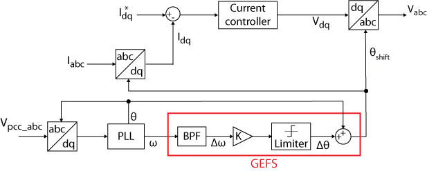
The effect of the phase shift depends on whether the grid is present or not. When the inverter is grid-connected, the stiff grid imposes the voltage and frequency at the point of common coupling (PCC). The band-pass filtered frequency remains close to zero, so \(\Delta\theta\) remains close to zero. A residual \(\Delta\theta\) only rotates the injected current relative to the grid voltage, which changes the reactive power exchanged with the grid.
When the inverter is islanded, the PCC voltage results from the inverter current flowing into the local load, and the load sets the phase between voltage and current. For a parallel RLC load with quality factor \(Q_f\), near its resonant frequency \(f_0\), the load phase angle \(\varphi_{load}\), defined as the angle by which the load current leads the voltage, is approximately
$$\varphi_{load} \approx 2 Q_f \, \frac{f – f_0}{f_0} \tag{2}$$
A phase shift \(\Delta\theta\) of the current must be balanced by the load phase angle, so the island frequency moves by approximately
$$\Delta f \approx \frac{f_0}{2 Q_f} \, \Delta\theta \tag{3}$$
The PLL measures this frequency change, and the GEFS loop increases \(\Delta\theta\) in the same direction. With a sufficient gain, this positive feedback drives the frequency outside the over- and under-frequency protection (OFP/UFP) limits. Equation (3) also shows why a high \(Q_f\) is the difficult case: the larger \(Q_f\), the smaller the frequency deviation produced by a given phase shift [3].
The signs of Eq. (2) and (3) follow the dq convention of the abc to dq0 (SD029) and dq0 to abc (SD030) transformations in imperix blocks. The PLL aligns the d-axis with the PCC voltage. With \(i_q^* = 0\), a positive \(\Delta\theta\) therefore makes the inverter current lead the PCC voltage by \(\Delta\theta\). Above resonance, the parallel RLC load is capacitive and its current leads the voltage, so a positive \(\Delta\theta\) raises the island frequency.
Applying the phase shift to the current controller frame
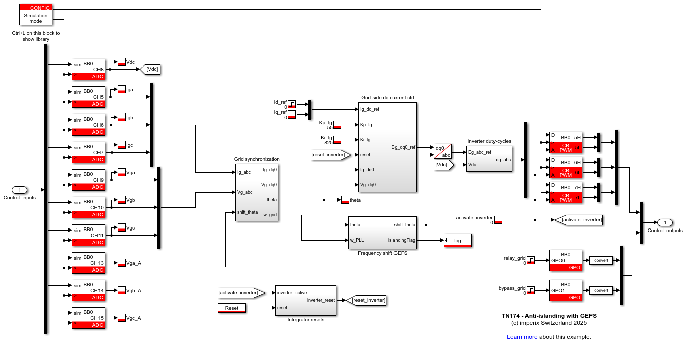
In the frequency-to-phase (\(\omega \rightarrow \theta\)) scheme of [3, Fig. A-5], the phase shift is applied only to the voltage transformation. The current controller then still measures the currents in the (real) PLL frame. A fast current controller sees the phase shift as a disturbance and compensates for it, so the current phase does not change, and the positive feedback does not close. For this reason, the phase shift must rotate the current controller’s entire frame. The shifted angle \(\theta_{shift}\) drives three transformations:
- the abc-to-dq transformation of the measured currents;
- the abc-to-dq transformation of the grid voltage used as voltage feedforward;
- the dq-to-abc transformation of the voltage reference.
The PLL keeps a separate abc-to-dq transformation driven by its own angle \(\theta\), because feeding \(\theta_{shift}\) back into the PLL input would create an algebraic loop and would also remove the frequency information that the GEFS loop needs.
Tuning of the GEFS loop
The GEFS loop has three tuning elements: the band-pass filter (1), the gain (2), and the limiter (3). They must keep the inverter stable when grid-connected, and make the frequency unstable fast enough to meet the 2s limit of IEEE 1547-2018 in islanding conditions [2].
Band-pass filter
The band-pass filter (BPF) solves two problems of the feedback loop. Its high-pass part removes the DC component of the frequency information, which would otherwise shift the phase permanently and degrade steady-state reference tracking. Its low-pass part attenuates measurement noise, which would otherwise degrade power quality. Given the 2s detection requirement, reference [3] uses a passband of 1Hz to 10Hz, which corresponds to response times between 0.1s and 1s.
The high-pass part also limits how long the frequency deviation is sustained. Once the island frequency settles at a constant deviation, the filter output decays, \(\Delta\theta\) returns to zero, and the frequency moves back toward \(f_0\). The protection must therefore trip the inverter as soon as the frequency exceeds the limits.
Gain
The gain \(K\) sets the strength of the positive feedback. When the inverter is grid-tied, the gain must be small enough to keep the control stable. When the inverter is islanded, the gain must be large enough to make the frequency unstable [3].
From Eq. (3), the required gain increases with the load quality factor. The PLL adds delay and attenuation to the loop, which further increases the required gain and slowing the build-up of frequency deviation after disconnection. The minimum gain therefore depends mainly on the PLL tuning, and the detection time depends on the PLL as well as on \(K\). The gain is therefore determined in simulation: \(K\) is increased until islanding is detected, and the final value is chosen well above this threshold so detection remains fast and reliable when operating conditions change.
Limiter
The limiter bounds the phase shift injected into the current controller. Two constraints set its value:
- When the inverter is islanded, the limiter must allow a frequency deviation larger than the protection threshold \(\Delta f_{trip}\). From Eq. (3), the limiter’s maximum deviation is \(\Delta f_{max} \approx f_0 \Delta\theta_{max} / (2 Q_f)\). With \(Q_f = 1\) and \(f_0 = 50\)Hz, a limiter of ±0.1rad allows a deviation of about 2.5Hz, which exceeds a ±1Hz protection threshold with a comfortable margin.
- When the inverter is grid-connected, a phase shift \(\Delta\theta\) of the current produces a reactive power of approximately \(P \tan \Delta\theta\), where \(P\) is the active power. A limiter of ±0.1rad keeps the power factor above 0.995. A wider limiter speeds detection but increases both the island’s frequency excursion and the reactive power GEFS can inject during grid disturbances.
GEFS anti-islanding technique implementation
The GEFS method is implemented in a Simulink model built with the ACG SDK, which generates code for imperix controllers from Simulink and PLECS models. The plant is modeled with the Power library. The results in this note are from simulation only. The model can be downloaded below.
Plant modeling and test case
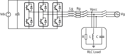
The test case follows the IEEE 1547.1 and IEC 62116 anti-islanding tests [5], [6], with limitations described in TN173. A three-phase voltage source inverter, as described in TN152, is connected to the grid through an RL filter, with a parallel RLC load at the PCC (Fig. 4). A breaker disconnects the grid at t =1s to create the island. The RLC load resonates at 49.95Hz, and its quality factor is \(Q_f =R\sqrt{C/L} = 1.0\), the value specified by the standards. Table 1 lists the model parameters.
| Parameter | Value | Parameter | Value |
|---|---|---|---|
| Grid phase-to-neutral RMS voltage \(V_g\) | 230V | Load resistance \(R\) | 12.3Ω |
| Grid frequency \(f_g\) | 50Hz | Load inductance \(L\) | 39.2mH |
| DC-bus voltage \(V_{dc}\) | 750V | Load capacitance \(C\) | 259µF |
| Filter inductance \(L_g\) | 2.2 mH | Load resonant frequency \(f_0\) | 49.95Hz |
| Filter resistance \(R_g\) | 33mΩ | Load quality factor \(Q_f\) | 1.0 |
Control structure
The inverter operates as a grid-following inverter. The currents are controlled in the dq frame, as described in TN106, with PI controllers implemented as in TN105. The PI gains are tuned with the magnitude optimum criterion. A PLL provides the grid angle and frequency, using \(K_p=0.01\) and \(K_i=1\). The control runs at 50kHz. The current references \(i_d^*=26.4\)A and \(i_q^*=0\)A produce the matched power for the test case.
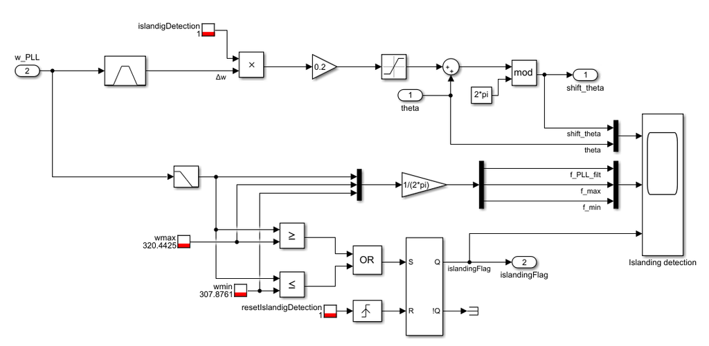
The GEFS subsystem implements Eq. (1) with a second-order band-pass filter, the gain \(K\) and a saturation block. The baseline tuning uses \(K=1\)s, a BPF centered at 10Hz with a damping of 0.707, and a limiter of \(\Delta\theta_{max}=\pm 0.1\)rad. The islanding detection compares the PLL frequency, low-pass filtered with a time constant of 0.1s, against the 49Hz and 51Hz limits. The filter prevents false trips: the raw PLL frequency contains ripple and short transients, for example after a phase jump of the grid voltage, which could briefly exceed the limits without islanding. A set-reset flip-flop latches the islanding flag.
In this model, the islanding flag does not stop the inverter, so that the frequency evolution remains visible after detection. In an application, the flag must stop the inverter, for example by disabling the PWM outputs through the Core state (SD026). Fig. 3 and Fig. 4 show the controller and the GEFS subsystem of the model.
Simulation results
All simulations use the plant and the control structure described above, with the baseline tuning except for the parameter under study. The breaker opens at t = 1s, after the start-up transients have settled. The figures show the low-pass-filtered PLL frequency used by the detection logic, so the detection times include the 0.1s delay of the detection filter. Each tuning parameter is varied separately, starting from the baseline tuning (\(K = 1\)s, \(\Delta\theta_{max} = \pm 0.1\)rad and a BPF centered at 10Hz).
Islanding with and without GEFS
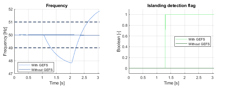
Fig. 5 compares the inverter response with and without GEFS. Without GEFS, the frequency remains within 0.04Hz of 50Hz after disconnection (t = 1s), close to the load’s resonant frequency. The island is not detected because the matched RLC load lies inside the OFP/UFP protection’s non-detection zone (NDZ). With GEFS, the frequency immediately deviates from the nominal value after disconnection and crosses the 49Hz limit. In the simulated test case, the GEFS loop detects islanding 0.30s after grid disconnection, well below the 2s limit of IEEE 1547-2018. The direction of the frequency excursion depends on the operating conditions at the instant of disconnection, as also reported in [3]. Both directions are detected because the protection monitors both limits.
Effect of the gain
Figure 6 compares four gain values for \(K\), using baseline parameters for the limiter and the BPF. With \(K = 0.1\)s, the frequency remains within 0.07Hz of 50Hz, and the island is not detected. With \(K = 0.2\)s, the frequency deviation builds up slowly, and the island is detected 1.16s after disconnection. With \(K = 1\)s and \(K = 5\)s, the island is detected 0.30s and 0.27s after disconnection.
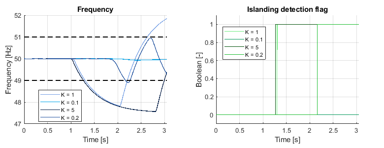
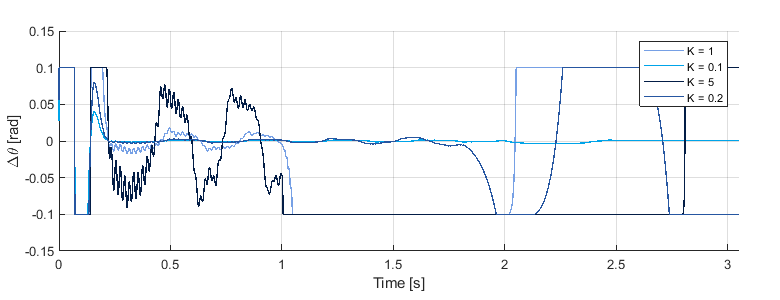
Close to the threshold, the gain sets the detection time. With \(K = 0.2\)s, the phase shift reaches the ±0.1rad limiter only 0.96s after disconnection, and the detection time of 1.16s leaves little margin to the 2s limit. Well above the threshold, a higher gain barely shortens the detection time, because the limiter saturates. Fig. 7 shows the limiter output \(\Delta\theta\). With \(K = 1\)s, \(\Delta\theta\) reaches the limit 47ms after disconnection. With \(K = 5\)s, it reaches the limit 6ms after disconnection. After that, \(\Delta\theta\) stays at the limit in both cases, so both inverters apply the same phase shift and the island frequency changes at the same rate (Eq. (3)). A higher gain only shortens the time needed to reach the limit.
A higher gain, however, increases the disturbance during grid-connected operation, as visible in Fig. 7 before t = 1s. Before disconnection, the phase shift oscillates within ±0.003rad with \(K = 0.2\)s, ±0.013rad with \(K = 1\)s, and ±0.09rad with \(K = 5\)s. The gain should therefore be chosen with a margin above the detection threshold, but not higher.
Effect of the limiter
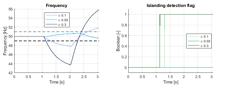
Figure 8 compares three limiter bounds, with the baseline gain and BPF. With a limiter of ±0.03rad, Eq. (3) predicts a maximum frequency deviation of about 0.75Hz, which is below the 1Hz protection threshold. In the simulation, the frequency deviates by at most 0.64Hz, and the island is not detected. This confirms the limiter rule of the tuning section. With ±0.1rad, islanding is detected 0.30s after disconnection, and the frequency deviates by up to 2.2Hz (bound from Eq. (3): 2.5Hz). With ±0.3rad, islanding is detected 0.13s after disconnection, but the frequency deviates by up to 6.2Hz (bound: 7.5Hz). A wider limiter therefore shortens the detection time at the cost of a larger frequency excursion of the island, and of a larger reactive power that GEFS can inject when grid-connected.
Effect of the band-pass filter
Figure 9 compares three BPF center frequencies, with the baseline gain and limiter. With BPF center frequencies of 3Hz and 10Hz, within the 1–10Hz range of [3], islanding is detected 0.29s and 0.30s after disconnection. With 30Hz, outside this range, the detection takes 0.58s, and the frequency response is more oscillatory.
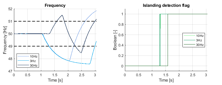
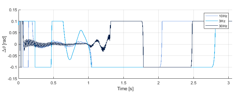
The PLL cannot follow fast frequency changes, so a BPF centered well above the frequency range that the PLL can track, attenuates the useful part of the feedback signal. A low center frequency, conversely, slows down the settling of the loop during grid-connected operation, as shown by the limiter output \(\Delta\theta\) in Fig. 10. With 3Hz, the phase shift remains at the limiter for about 0.6s after start-up, and still varies within ±0.1rad before disconnection, whereas it remains within ±0.013rad with 10Hz. A center frequency close to the upper end of the 1–10Hz range is therefore a good compromise in this model.
Conclusions
The GEFS anti-islanding method detects an unintentional island by destabilizing its frequency with a positive-feedback loop from the measured frequency to the phase angle. When the inverter is grid-connected, the stiff grid keeps the frequency constant, and the loop remains inactive. When the inverter is islanded, the phase shift shifts the local load frequency, and the loop amplifies the deviation until over- or under-frequency protection trips.
The frequency-to-phase scheme of [3] requires one modification when the current controller is fast: the phase shift must rotate the entire current controller frame, including the current measurement and the voltage feedforward, while the PLL keeps its own angle. If the shift is applied only to the voltage reference, the current controller compensates for it, and the positive feedback does not close.
Tuning the band-pass filter, gain, and limiter involves a trade-off between grid-connected operation and islanding detection. The gain must be large enough to destabilize the island frequency, which depends mainly on the PLL dynamics and is found in simulation, but higher-than-necessary gain increases disturbance during grid-connected operation. The limiter must allow a frequency deviation larger than the protection threshold, while limiting the reactive power injected during grid-connected operation. The BPF center frequency must lie within the 1–10Hz range of [3]: low enough to pass the frequency variations that the PLL can track, but high enough for the loop to settle quickly after start-up and grid transients.
References
[1] Ê. C. Resende, M. G. Simões, and L. C. G. Freitas, “Anti-islanding techniques for integration of inverter-based distributed energy resources to the electric power system,” IEEE Access, vol. 12, 2024.
[2] IEEE Standard for Interconnection and Interoperability of Distributed Energy Resources with Associated Electric Power Systems Interfaces, IEEE Std 1547-2018, 2018.
[3] Z. Ye, R. Walling, L. Garces, R. Zhou, L. Li, and T. Wang, “Study and development of anti-islanding control for grid-connected inverters,” National Renewable Energy Laboratory, Golden, CO, USA, Rep. NREL/SR-560-36243, May 2004.
[4] Z. Ye, A. Kolwalkar, Y. Zhang, P. Du, and R. Walling, “Evaluation of anti-islanding schemes based on nondetection zone concept,” IEEE Trans. Power Electron., vol. 19, no. 5, pp. 1171–1176, Sep. 2004.
[5] IEEE Standard Conformance Test Procedures for Equipment Interconnecting Distributed Energy Resources with Electric Power Systems and Associated Interfaces, IEEE Std 1547.1-2020, 2020.
[6] Utility-interconnected photovoltaic inverters – Test procedure of islanding prevention measures, IEC 62116:2014, 2014.