Table of Contents
This technical note introduces the working principle of a Grid-Following Inverter (GFLI) and presents an implementation example built with the TPI 8032 programmable inverter.
What is a Grid-Following Inverter?
Grid-Following Inverters (GFLI) and Grid-Forming Inverters (GFMI) are two basic categories of grid-connected inverters. Essentially, a grid-following inverter works as a current source that synchronizes its output with the grid voltage and frequency and injects or absorbs active or reactive power by controlling its output current. In contrast, a grid-forming inverter works as a voltage source that sets the amplitude and frequency of the grid, as introduced in Grid-Forming Inverter.
Thanks to the advantages of simplicity and relatively low price, grid-following inverters are widely used in grid-connected applications, such as renewable energy generation, energy storage, electric vehicle charging, etc. Compared to grid-forming inverters, grid-following inverters can achieve faster power control and response, and also avoid some technical challenges such as synchronization between parallel-operating inverters.
Control of the Grid-Following Inverter
The control objective of a Grid-Following Inverter is usually to control the active and reactive power injection to the grid. In a rotating reference frame (dq) synchronized with the grid voltage, the active and reactive power can be expressed as:
$$P = \frac{3}{2}\cdot V_{g,d}\cdot I_{g,d}$$
$$Q = \frac{3}{2}\cdot V_{g,q}\cdot I_{g,q}$$
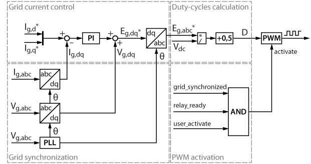
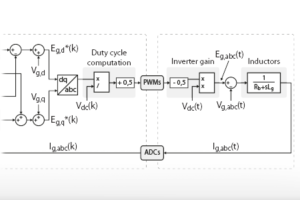
If the grid voltage amplitude \(V_{g,d}\) is constant, the control of the active and reactive power can be simplified with the control of the grid currents in the dq-frame. In addition to the current control loop, some additional functionalities are also needed, such as synchronization with the AC grid and proper activation of the PWM outputs, as depicted in the control diagram below.
Grid synchronization
An accurate synchronization system is required to track the grid’s phase and frequency. This note uses an SRF PLL as an example, which is a simple and widely used solution for synchronization with the three-phase grid. Another possible technique is introduced in SOGI PLL, which has better dynamic performance and can work with a single-phase grid, at the cost of a more complex implementation.
Grid current control
In this note, the active and reactive power flow is directly controlled by the current reference \(I_{g,d}\) and \(I_{g,q}\) in the rotating reference frame (dq). The grid current components are controlled by two PI controllers in the grid-synchronous frame (dq) using the same technique as introduced in Vector current control.
The plant model of the current controller contains multiple terms, in part due to the multi-stage filter of the TPI 8032. However, for the tuning purpose of the current controller, this plant model can be simplified to a first-order delay representing the actuator, and a sole inductor. The resulting plant transfer function is therefore:
$$G_{plant}(s)=\frac{1}{1+sT_d}\cdot\frac{1}{R_g+sL_g}$$
The control parameters \(K_{p,I}\) and \(K_{i,I}\) can, for instance, be tuned using the Magnitude Optimum (MO) criterion, considering the plant model above and the parameters \(L_g\) and \(R_g\) extracted from to the TPI 8032 datasheet.
$$\begin{aligned} K_{p,I} =\frac{L_g}{2T_d} \\ \\ K_{i,I} =\frac{R_g}{2T_d}\end{aligned}$$
| Lg | 1050 µH |
| Rg | 54 mΩ |
The parameter \(T_{d}\) represents the sum of all the small delays in the system, such as the computation and the modulation delays. The product note Time delay determination for closed-loop control explains how to determine the total delay of the system. In this example, the cycle delay is shorter than half a control period (\( T_{cy} < 0.5T_s \)), and a triangular carrier is used for PWM modulation. The delay total delay \(T_{d}\) is computed as follows:
- Sensing delay: neglected (\(\approx 500\,\text{ns}\))
- Control delay: \(T_{d,ctrl} = 0.5T_s\)
- Modulator delay: \(T_{d,\text{PWM}}=0.5T_{sw}\)
- Switching delay: neglected, sub-microsecond
Please also note that if synchronous averaging is enabled, which is the case by default in TPI ADC blocks, an additional delay of \(0.5T_{sw}\) has to be considered, due to the averaging of the measured quantities over one switching period. When considering \(T_s = T_{sw}\), the total delay is therefore:
$$ T_{d}=T_{d,ctrl} + T_{d,\text{PWM}} + T_{d,\text{avg}}=1.5T_s $$
PWM activation
The PWM output is only activated when:
- PLL is synchronized with the grid;
- Relays are closed and ready to operate;
- The tunable parameter
activateis set to ‘1’ by users.
TPI 8032 implementation
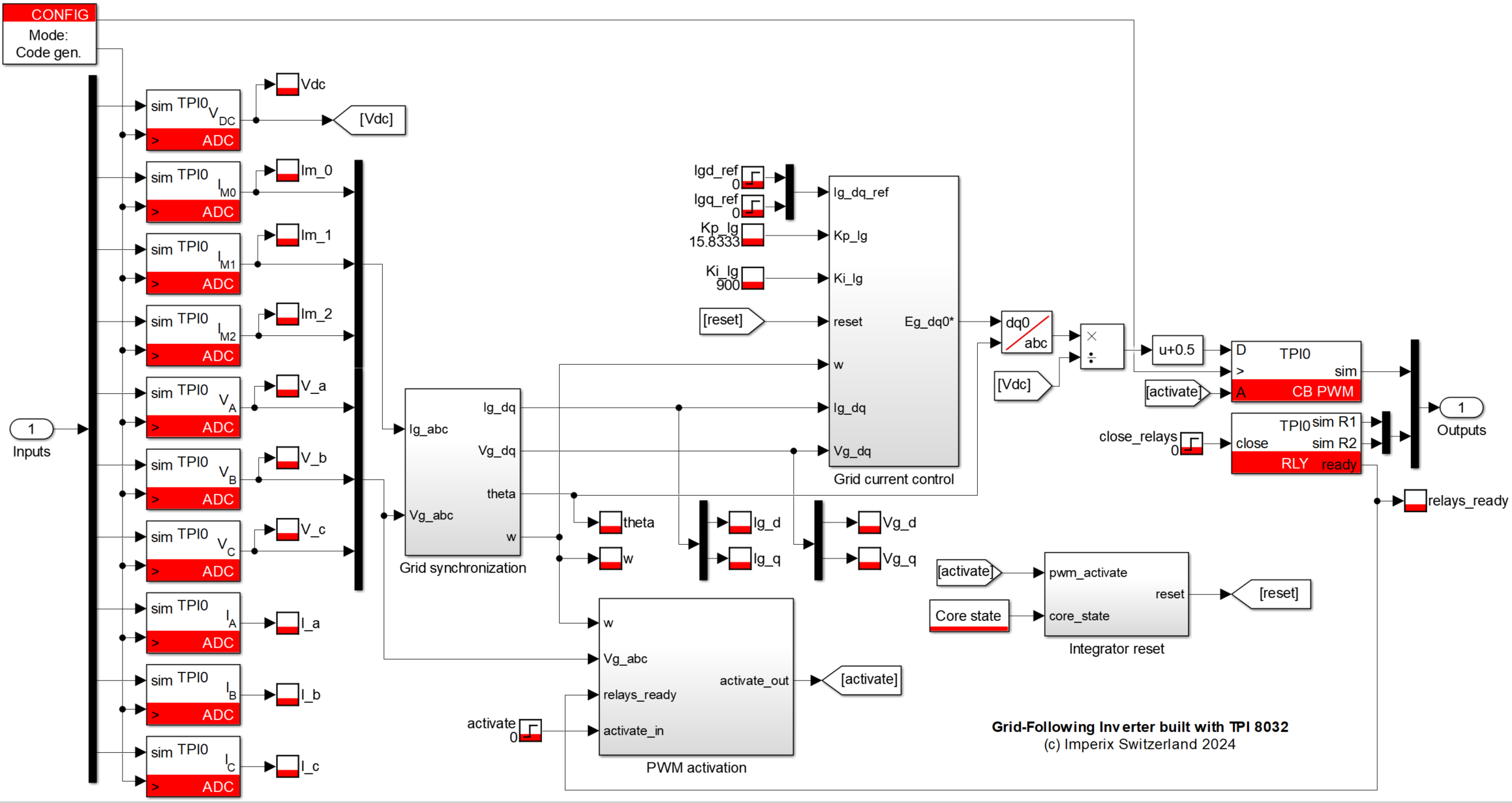
The Grid-Following Inverter control has been implemented in Simulink.
Software resources
The following zip files contain examples of control using MATLAB Simulink and PLECS.
Imperix Power library requires ACG SDK 2024.2 or a later version. To update the ACG SDK, please go to imperix.com/downloads/.
The minimum requirements are:
- Imperix ACG SDK 2024.2 or newer, available here
- MATLAB Simulink R2016a or newer.
- Plexim PLECS 4.5 or newer
- For simulation only: Simscape Electrical
Experimental results
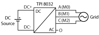
The experiment has been carried out on a TPI 8032 with a DC source and AC grid. The wiring scheme and the experiment setup are shown below.
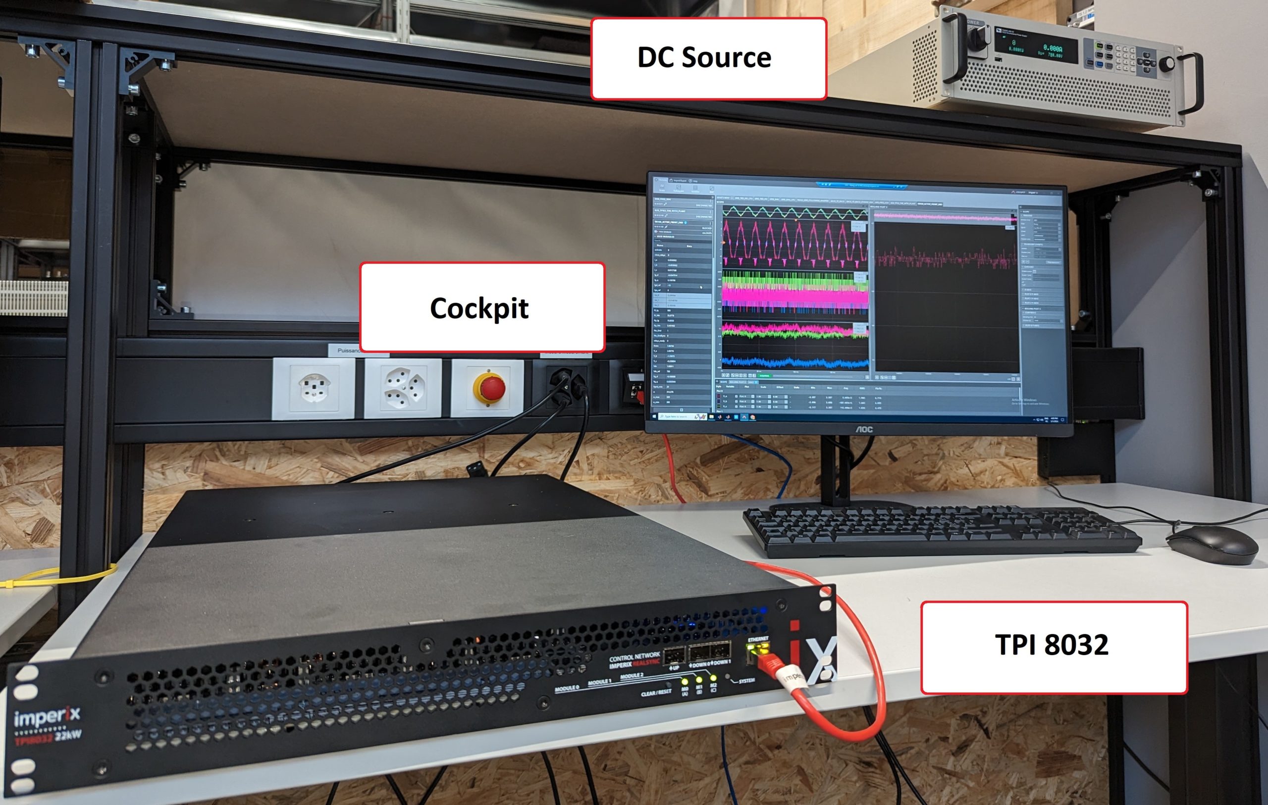
The operating conditions are:
| Control frequency [kHz] | 50 |
| DC bus voltage [V] | 750 |
| RMS grid voltage (phase to neutral) [V] | 230 |
| Grid frequency [Hz] | 50 |
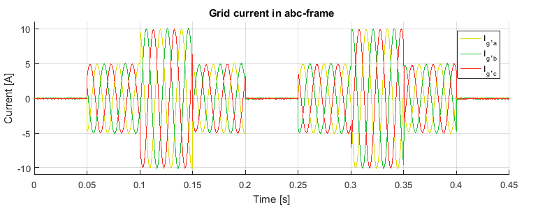
The experimental results are presented below with steps performed on the d-axis and q-axis current reference. It can be seen that the current reference is rapidly tracked by the controller during the whole test.
Besides, the controller also has good performance in decoupling d-axis and q-axis currents. When there is a current step in one axis, the current in the other axis remains unaffected.
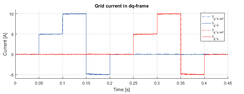
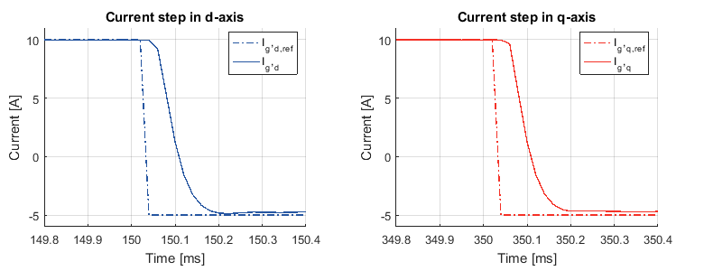
The controller’s time-domain performance can be further verified by examining one step on the d-axis or q-axis more closely. As seen in the following figure, the settling time is around 200 us. The controller has fast performance with no overshoot.
To go further
The TPI 8032 can be easily programmed to fit any purpose. More examples of TPI in microgrid applications are available in the knowledge base, such as:
Additionally, a grid-following example using a B-Board and a third party inverter is provided in TN178.


