Table of Contents
This technical note presents a possible implementation of a V/f control of an Induction Machine (IM).
First, the note introduces the concepts behind the V/f control in open-loop. Then, it continues on a closed-loop variant to improve the tracking performance of the speed control.
Finally, a practical control implementation is introduced, targeting the B-Box RCP or B-Board PRO with the ACG SDK on Simulink. Please note that imperix offers a ready-to-use motor drive system to develop and test motor control techniques. More details can be found in the Motor Testbench quick start guide (PN181).

General principles of V/f control
The V/f method is a form of scalar control [1] because it relies only on the magnitude of the stator voltage. This contrasts with vector control methods [1] that use both the magnitude and the phase.
In the stator flux reference frame, the equation of the stator circuit is [2]:
$$(1) \qquad \underline{V}_{dqs} = R_s \underline{I}_{dqs} + \frac{d \underline{\Psi}_{dqs}}{dt} + j \omega _s \underline{\Psi}_{dqs}$$
In steady-state, it becomes:
$$(2) \qquad \underline{V}_{dqs} = R_s \underline{I}_{dqs} + j \omega _s \underline{\Psi}_{dqs}$$
If we neglect the voltage drop over the stator resistance and consider only the magnitude:
$$(3) \qquad \Psi_{dqs} \approx \frac{V_{dqs}}{\omega _s}$$
Consequently, the stator flux can be maintained constant by keeping the V/f ratio constant. In this case, the speed of the machine becomes proportional to the stator voltage.
The V/f method only controls the speed of the machine, according to (3). The machine will naturally adjust its torque to the load. However, there is no explicit torque control.
V/f profile
The basic idea of a V/f control is to maintain the stator flux constant. To operate the machine under nominal conditions, the stator flux must be nominal.
$$(4) \qquad \Psi_{dqs}^* = \Psi_{dqsn} \approx \frac{\sqrt{2} V_{sn}}{\omega _{sn}}$$
with \(V_{sn}\) the nominal RMS phase voltage. Then, from (3) and (4), the speed reference can be converted into a voltage reference:
$$(5) \qquad V_{dqs}^* \approx \Psi _{dqs}^* \omega _s^* = \frac{\sqrt{2} V_{sn}}{\omega _{sn}} \space \omega _s^*$$
Low-speed operation – Dead zone
The relation in (3) was established assuming that the voltage drop over the stator resistance could be neglected. However, this hypothesis does not hold at low speeds because the voltage drop becomes comparable to \(V_{dqs}\) in amplitude [3]. In this situation, the stator voltage should be increased to compensate for the voltage drop. This means the V/f ratio is not constant at low speeds [3].
High-speed operation
If the machine operates above the nominal speed, the stator voltage should exceed its nominal value according to (3). To prevent an overvoltage, the voltage reference should be saturated to \(V_{sn}\). As a result, the stator flux drops below its nominal value at high speed. This is commonly called the field-weakening region of operation [3].
The constant flux, dead zone, and field-weakening regions are illustrated in the voltage profile below. It links the amplitude and the frequency of the stator voltage.
Closed-loop version of V/f control
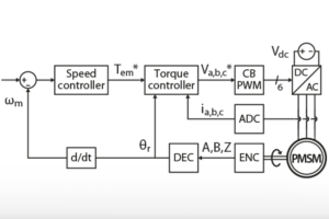
V/f links voltage amplitude and frequency. However, speed control cannot be directly achieved because of slip. In this note, the slip frequency is compensated by a PI regulator. The technical note TN114 explains how to implement a closed-loop speed control for any type of motor. However, it assumes that the inner-loop is a torque controller which is not the case with a V/f control. Therefore, the PI cannot be tuned the same way as in TN114.
Fortunately, there is a workaround for an IM: usually, the speed reference is the mechanical speed of the rotor. Since the V/f profile expects the stator electrical speed as an input, there is a tracking error that is equal to the slip speed in open-loop. In closed-loop control, the slip speed can be compensated by a PI controller.
Since the V/f is intended to be a simple speed control method, the PI controller can be tuned “by hand” when the motor is up and running.
B-Box / B-Board implementation of V/f control
Software resources for V/f control
- TN138_Motor_TB_no_load_test_v2 deals with the open-loop V/f control of a single induction machine with no load.
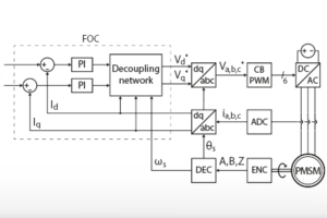
- TN138_Motor_TB_load_test _v2.1 additionally includes a torque-controlled PMSM. The Field-Oriented Control (FOC) of the PMSM is presented in TN111.
Imperix Power library requires ACG SDK 2024.2 or a later version. To update the ACG SDK, please go to imperix.com/downloads/.
V/f profile
The V/f profile is a linear relation with a dead zone at low speed and saturation at high speed. Thus, the Simulink implementation is straight forward as shown below.
Calculation of the duty cycles
According to (5), the output of the V/f profile is the norm of the voltage reference. It is then converted into three sinusoidal waveforms of frequency \(\omega_s^*\) and fed to a Carrier-Based PWM modulator. The generation of the variable frequency sinewaves relies on an oscillator using a phase accumulator, as shown below.
Speed controller
The figure illustrates the implementation of the speed controller. It consists of a simple PI controller with anti-reset windup. The proportional and integral gains were tuned manually through offline simulation. This is made possible thanks to the faithful modeling of the controller dynamics in the ACG SDK library blocks.
The torque-slip characteristic and the parameters of the IM are not known with a V/f control. Therefore, the breakdown slip [2] was assumed to be \(s_b=0.05\). Since the output of the controller is a slip frequency, the breakdown slip is set as the saturation limit of the PI.
Notice that the PI is held at reset when the machine is in the dead zone. This way, the integral term does not accumulate the tracking error when the IM cannot move anyway.
Experimental results of V/f control
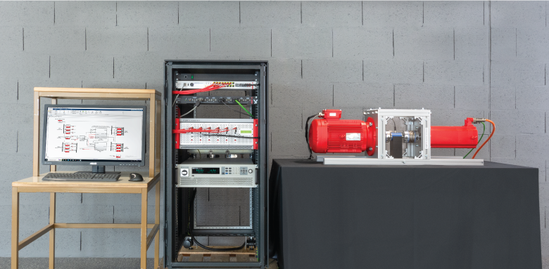
The experimental setup consists of an induction machine and a permanent magnet synchronous machine (PMSM). The PMSM is used to apply a load torque on the IM. Each machine is supplied by a voltage source inverter made of 3x PEB 8032 phase-leg modules . The control code of each machine is implemented on Simulink, using the ACG SDK library, and both algorithms run on a single B-Box RCP controller.
The following experimental results are all exported from the datalogger of the BB Control software (now replaced by Cockpit) and post-processed using MATLAB.
Machine parameters
The parameters of the induction machine are given in the table below. The PMSM (Control Techniques 115UMC300CACAA) was chosen to operate under the same nominal conditions.
| Model: Leroy-Somer 2P LSES 100L 3kW | |||
| Parameter | Symbol | Value | Unit |
| Rated power | \(P_n\) | 3 | kW |
| Pole pairs | \(p\) | 1 | – |
| Rated phase voltage | \(V_{sn}\) | 230 | V |
| Rated phase current (wye-connected) | \(I_{sn}\) | 6.1 | A |
| Rated mechanical speed | \(\Omega_n\) | 2870 | rpm |
| Rated torque | \(T_{em,n}\) | 9.95 | Nm |
| Rated power factor | \(\cos \phi\) | 0.88 | – |
| Stator resistance | \(R_s\) | 1.5 | Ω |
| Stator inductance | \(L_s\) | 307 | mH |
| Rotor resistance* | \(R_r\) | 1.4 | Ω |
| Rotor inductance* | \(L_r\) | 313 | mH |
| Mutual inductance | \(L_m\) | 295 | mH |
| Moment of inertia (IM only) | \(J_m\) | 0.0036 | kg m2 |
* The rotor variables are referred to the stator side.
Speed tracking
The tracking performance of the speed controller was validated experimentally by applying a speed reference step from 0 to 2870 rpm. At the same time, the PMSM was applying a load torque proportional to the speed. In the end, the IM was operating at nominal speed and with a load of 9.5 Nm in steady-state.
In a practical situation, a motor cannot accelerate instantaneously to its nominal speed because of its inertia and limited power. Therefore, there is no point in applying a step reference from 0 to 2870 rpm. Instead, a rate limiter was applied during the experiment to limit the acceleration to 2870 rpm/s.
The figure below shows the performances of the speed control in both open- and closed-loop. In open-loop, the V/f method has no notion of slip. Therefore, under load, there is inevitably a permanent tracking error due to the slip (~2.4% in this case). In close-loop however, the PI controller estimates the slip and corrects the speed reference accordingly. This way, the control can eliminate the permanent tracking error.

Since this is an induction machine, the rotor mechanical speed \(\omega_m\) is slower than the rotor flux \(\omega_r\) under load (see below on the left). Let us recall the definition of the relative slip [3]:
$$(6) \qquad s = \frac{\omega _r – \omega_m}{\omega_r}$$
At startup, the slip should be equal to 1 because the rotor is at a standstill. Then, the machine should quickly move to a stable operating point with a low slip as illustrated below (right). However, this is not exactly what happens with the slip frequency estimation. Indeed, the slip is estimated, not from the model of the IM, but by the speed controller. This has two consequences: (a) since the integral term is held in reset in the dead zone, the slip estimation is invalid in this region, and (b) the convergence of the slip estimation towards the true value depends heavily on the integral action. During the experiment, the gains were \(K_p=0.1\) and \(K_i=3\), and it took ~50ms to converge to the true value of the slip when exiting the dead zone.

Disturbance rejection
It was shown previously that the speed controller can track the speed reference. However, it should also be capable of rejecting a disturbance (i.e. a load torque). To verify the disturbance rejection, the speed of the IM was ramped up to 2870 rpm under no load. Then, a step from 0 to 9.5Nm was applied by the PMSM.
The presence of a load torque increases the slip. Therefore, the speed reference should be increased by the slip frequency to compensate. This is exactly what is done by the speed controller as shown below (left): the mechanical speed of the rotor drops by ~6.2% and it takes ~1.75s to recover from the load step. In open-loop however, there is no feedback of any kind and, consequently, no disturbance rejection. As explained in the previous section, this results in a permanent tracking error under load.

Notice that, if the speed tracking error is low, the integral gain must be large to enable a fast convergence of the slip estimation. Unfortunately, \(K_i\) cannot be arbitrarily large because it also impacts the stability of the control. Thus, in the situation presented above, the real slip changes abruptly with the load step, but the variation of the estimate is slow because it is limited by the dynamic of the PI controller.
Academic references
[1] Nguyen Phung Quang, Jörg-Andreas Dittrich, “Vector Control of Three-Phase AC Machines”, Springer, 2015, ISBN 978-3-662-46914-9
[2] Slobodan N. Vukosavic, “Electrical Machines”, Springer, 2013, doi: 10.1007/978-1-4614-0400-2
[3] Z. Zhang, Y. Liu and A. M. Bazzi, “An improved high-performance open-loop V/f control method for induction machines,” 2017 IEEE Applied Power Electronics Conference and Exposition (APEC), Tampa, FL, 2017, pp. 615-619, doi: 10.1109/APEC.2017.7930757.


