Table of Contents
This technical note presents a common control technique for Permanent Magnets Synchronous Machines (PMSM). The Field-Oriented Control (FOC) method is a motor control strategy that orients the stator current vector in a rotating reference frame of the machine. First, the note introduces the general operating principles of the Field-Oriented Control and then, details a possible design methodology. Finally, a practical control implementation is introduced to drive the machine with a power inverter, controlled either by the B-Box RCP or the B-Board PRO. Please note that imperix offers a ready-to-use motor drive system to develop and test motor control techniques. More details can be found in the Motor Testbench quick start guide (PN181).
General principles of field oriented control
The Field Oriented Control (FOC) is a form of vector control [1]. The machine currents, voltages, and magnetic fluxes are expressed as space vectors inside a Rotating Reference Frame (RRF). In the case of a synchronous machine, the stator and rotor fluxes are synchronous [2]. Therefore, a natural choice is to orient the RRF such that its d-axis is aligned with the rotor flux. The rotor position must be known to orient the RRF. The position is either measured with an encoder or estimated with a sensorless technique. Both options are presented in PN104 and TN136, respectively. The working principle of FOC relies on the machine’s equations in that RRF. Let us first consider the stator equations of an isotropic PMSM in the RRF [2]:
$$(1) \qquad \begin{array} \displaystyle U_{ds} &= R_s I_{ds} + \cfrac{d \Psi _{ds}}{dt} – \omega _s \Psi _{qs}\\[5pt] \displaystyle U_{qs} &= R_s I_{qs} + \cfrac{d \Psi _{qs}}{dt} + \omega _s \Psi _{ds}\\[5pt] \displaystyle \Psi _{ds} &= L_d I_{ds} + \Psi _{PM} \\[5pt] \displaystyle \Psi _{qs} &= L_q I_{qs} \end{array}$$
Let us also consider the expression of the torque [2]:
$$(2) \qquad T_{em} = \frac{3}{2} p (\Psi _{ds} I_{qs} – \Psi _{qs} I_{ds})$$
Since the machine is assumed to be isotropic, \(L_d = L_q = L_s\), the equations from (1) and (2) can be re-arranged as such:
$$(3) \qquad \begin{array} \displaystyle I_{ds}^* &= \cfrac{\Psi _{ds}^* – \Psi _{PM}}{L_s} \\[5pt] \displaystyle I_{qs}^* &= \cfrac{T_{em}^*}{\frac{3}{2} p \Psi _{PM}} \end{array}$$
Equation (3) shows that the stator flux (d-axis component) and the torque can be controlled independently by the current \(I_{ds}\) and \(I_{qs}\), respectively. The torque control sets the stator flux q-axis component since it is proportional to \(I_{qs}\).
System-level modeling of the field oriented control algorithm
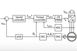
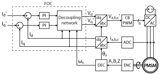
The independent control of \(I_{ds}\)and \(I_{qs}\) can consist of two PI regulators with a decoupling network, as any vector control strategy [1]. The FOC algorithm usually generates voltage references that a PWM modulator transforms into gating signals for a voltage source inverter. In the present implementation, the rotor position measurement is derived from an incremental encoder. The figure below shows the complete block diagram of the implementation, with a carrier-based PWM modulator and an encoder/decoder module. Please note that space vector modulation could alternatively be used to improve the DC bus utilization.
A more intuitive approach
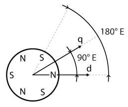
The d and q axes of a rotating reference frame have a physical meaning in the case of an electrical machine: the d-axis is directly aligned on a rotor magnetic pole and the q-axis is shifted from 90°E (electrical degrees), thus the name quadrature axis. As always, two magnetic poles of opposite polarity are shifted by 180°E.
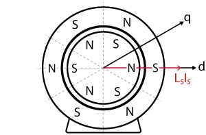
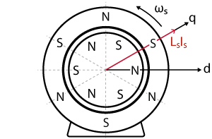
Referring to equation (1), the total stator flux \(\Psi _s\) is divided into two parts: the flux \(L_s \, I_s\) due to the stator current and the contribution \(\Psi _{PM}\) from the rotor. If the magnetic poles of the stator are aligned with their opposite poles on the rotor, the system is at equilibrium and the stator flux vector \(L_s \, I_s\) is aligned on the d-axis. Conversely, if the magnetic poles of the stator are not aligned with their opposite counterparts, their attractive and repulsive forces generate a torque on the rotor. In this case, the stator flux \(L_s \, I_s\) is not aligned with the d-axis, and the angle difference between the two – commonly called the load angle (or power angle) [3] – is non-zero. In summary, the q-axis component of the stator flux contributes to the torque generation and the d-axis component only magnetizes the machine.
Flux and torque control
Plant model
The phases of a PMSM at the stator being essentially RL circuits, the transfer functions linking the voltage to the current are:
$$(4) \qquad \begin{array}{ll} H_d(s) &= \cfrac{I_{ds}(s)}{U_{ds}(s)} = \cfrac{1/R_s}{1 + s \space L_d/R_s} = \cfrac{K_1}{1 + s \space T_1}\\[5pt] H_q(s) &= \cfrac{I_{qs}(s)}{U_{qs}(s)} = \cfrac{1/R_s}{1 + s \space L_q/R_s} = \cfrac{K_2}{1 + s \space T_2} \end{array}$$
Field oriented control implementation
The stator currents control consists of two digital PI controllers. Since the d and q axes are coupled, a decoupling network is necessary to achieve independent control of each current component, as developed in TN106. The PI regulators can be tuned using the magnitude optimum criterion [4][5]:
$$(5) \qquad \left\{ \begin{array} \displaystyle T_n &= T_1\\[5pt] \displaystyle T_i &= 2 \space K_1 \space T_{tot} \\[5pt] \displaystyle K_p &= T_n \space / \space T_i \\[5pt] \displaystyle K_i &= 1 \space / \space T_i \end{array} \right.$$
The parameter \(T_{tot}\) represents the sum of all the small delays in the system. The product note PN142 explains how to determine the total delay of the system. A numerical example is given below.
Flux reference
The field-oriented control (FOC) is mainly used as a torque controller. Therefore the d-axis current reference is usually set to zero, to maximize the torque production [1]. However, some flux optimization techniques set the d-axis current to a non-zero reference. For example, field weakening techniques reduce the stator flux on the d-axis to operate above the nominal speed.
B-Box / B-Board implementation
Software resources
ACG SDK for Simulink
Current controller for field oriented control
The figure below shows a possible implementation of a current controller for FOC with Simulink. One can identify the two PIs for the d and q axes and the decoupling network in between. The saturation limits of the PIs are set dynamically, depending on the DC bus voltage.

Tuning of the PI controllers
Here is a complete numerical example of how to tune the PI controllers of the FOC. The machine parameters are presented in the Experimental results section. Since the available PMSM is isotropic, the inductance is the same on the d and q axes. Therefore, both PIs have the same following transfer function and the same tuning.
$$(6) \qquad H_d(s) = H_q(s) = \frac{1/R_s}{1 + s \space L_d/R_s} = \frac{K_1}{1 + s \space T_1} = \frac{0.294 \space \Omega ^{-1}}{1 + s \space 3.57 \,\text{ms}}$$
As explained in the PN142, the execution of the digital control is affected by a delay along the control chain. It can be subdivided into the following delays:
$$(7) \qquad \left\{ \begin{array} \displaystyle T_{sens} \approx 0 \\[5pt] \displaystyle T_{ctrl} = T_s = \cfrac{1}{20 \, \text{kHz}} = 50 \,\text{µs}\\[5pt] \displaystyle T_{PWM} = \cfrac{T_{sw}}{2} = \cfrac{1}{2 \times 20 \, \text{kHz}} = 25 \,\text{µs} \end{array}\right.$$
According to the information provided by imperix Cockpit (formerly the Timing info tab in BB Control), the cycle delay is less than 20% of a sampling period. Since the sampling phase was set to \(\phi_s=0.5\), the condition \(T_{cy}<(1−\phi_s)T_s\) is true. That is why the control delay is only 1 switching period.
The total delay is then the sum of the small time constants:
$$(8) \qquad T_{tot} = T_{sens} + T_{ctrl} + T_{PWM} = 75 \,\text{µs}$$
According to the magnitude optimum criterion, the parameters of the PIs are computed as:
$$(9) \qquad \begin{array} \displaystyle T_n &= T_1 = 3.57 \,\text{ms} \\[5pt] \displaystyle T_i &= 2 \space K_1 \space T_{tot} = 4.41 \times 10^{-5} \,\Omega ^{-1}\,\text{s}\\[5pt] \displaystyle K_p &= T_n \space / \space T_i = 80.95 \,\Omega\\[5pt] \displaystyle K_i &= 1 \space / \space T_i = 22675.7\,\Omega\,\text{s}^{-1} \end{array}$$
Experimental results of the field oriented control
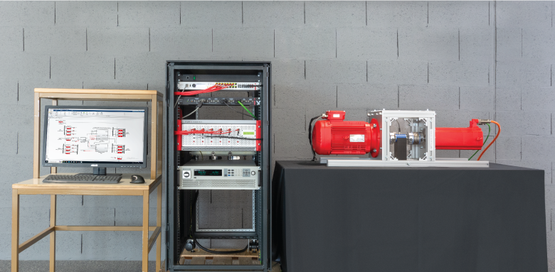
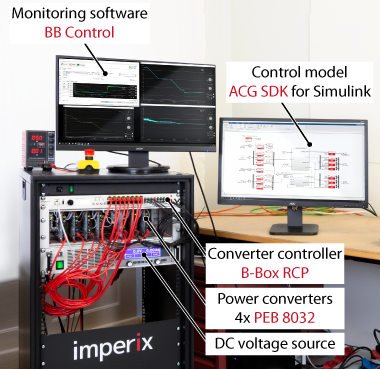
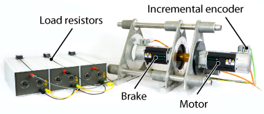
The experimental setup consists of a PMSM supplied by a voltage source inverter controlled by a B-Box prototyping controller. The FOC algorithm is implemented using the graphical programming of the ACG SDK library for Simulink. The power converter is built from 4x PEB 8032 phase-leg modules (3 phases and 1 braking chopper leg). Another PMSM connected to 3 power resistors is used as a brake to generate a load torque.
Machine parameters
The implemented field-oriented control algorithm was validated experimentally on a Unimotor fm servomotor from Control Techniques.
| Parameter | Value | Unit |
| Rated power | 1.23 | kW |
| Pole pairs | 3 | – |
| Rated phase voltage | 460 | V |
| Rated phase current | 2.7 | A |
| Rated mechanical speed | 314 | rad/s |
| Rated torque | 3.9 | Nm |
| Stator resistance | 3.4 | Ohm |
| Stator inductance (d and q axis) | 12.15 | mH |
| Permanent magnet flux | 0.25 | Wb |
| Moment of inertia (PMSM only) | 2.9 | kg cm2 |
Test conditions
- Load torque: 3.9 Nm (PMSM with resistors as load)
- Inverter DC link voltage: 500 V
- Control and sampling frequency: 20 kHz
- Sampling phase: 0.5
- PWM outputs: carrier-based
- Current measurements filtered with a 1.6 kHz cut-off frequency (using the front panel of the B-Box RCP)
Experimental results of field oriented control
The tracking performance of the torque control was validated experimentally on a modular three-phase inverter by performing a reference step from -1 Nm to 3.9 Nm (nominal torque). The current controllers on both axes can follow their respective references with fast dynamics and no overshoot.

The corresponding phase currents are also shown below. Since the current on the d-axis is zero, the q-axis current corresponds to the envelope of the phase currents.

Academic references
[1] Nguyen Phung Quang, Jörg-Andreas Dittrich, “Vector Control of Three-Phase AC Machines”, Springer, 2015, ISBN 978-3-662-46914-9
[2] Slobodan N. Vukosavic, “Electrical Machines”, Springer, 2013, DOI 10.1007/978-1-4614-0400-2
[3] Jan A. Melkebeek, “Electrical Machines and Drives: Fundamentals and Advanced Modelling”, Springer, 2018, ISBN 978-3-319-72729-5
[4] Hansruedi Bühler, “Réglage de systèmes d’électronique de puissance – Volume 1: théorie”, Presses Polytechniques et Universitaires Romandes, 1997, ISBN-10: 2-88074-341-9
[5] Karl J. Åström and Tore Hägglund; “Advanced PID Control”; 1995