Table of Contents
Double pulse testing is a widely utilized method to evaluate the switching behavior of power semiconductor devices, such as MOSFETs and IGBTs, as well as the recovery characteristic of body diodes. A double-pulse test can be carried out either in an early design stage to test a power stack under worst-case conditions, or later on, to asses switching times and switching losses of the device under test (DUT).
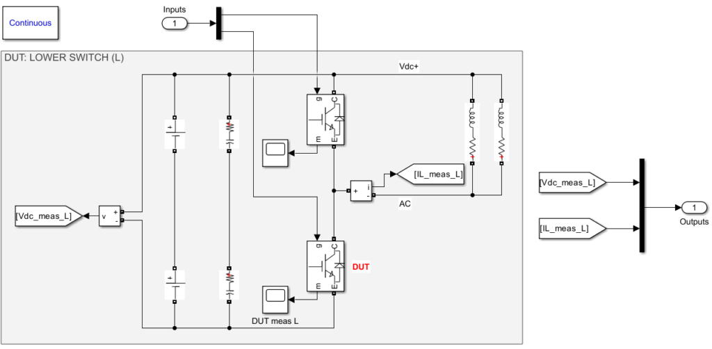
This technical note introduces the double pulse test. The DUT is the lower power switch (Infineon IKW75N65EH5XKSA1) mounted on the imperix PEB4050 IGBT power module. The test code is implemented on the B-Box RCP using ACG SDK.
Double pulse testing with imperix modules
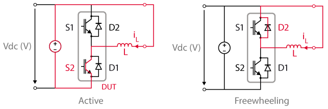
The PEB4050 power module is a two-level converter. During the fundamental cycle of a two-level converter, the operation of the controller changes between buck (S1 and D1 active) and boost (S2 and D2 active) modes, depending on the direction of the current flow, creating commutations events from switch to diode or vice versa in each operating mode. The double pulse testing allows for the measurements of switching times and losses for all these commutations. Only the boost mode is illustrated in the following figure, as it is the tested scenario.
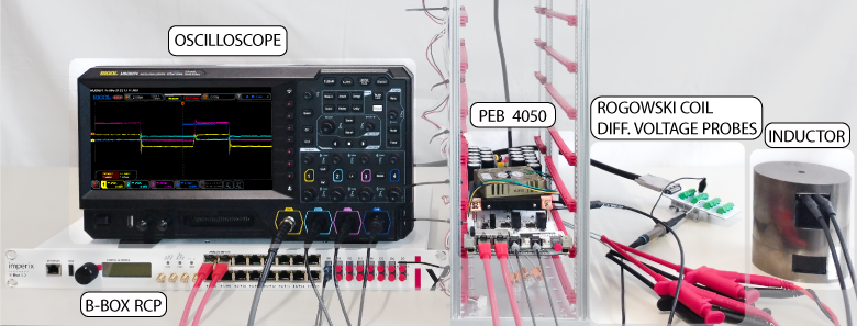
The DPT setup is presented in the following figure. The same DPT can be carried out using single-ended voltage probes by grounding the negative DC terminal.
Here, the B-Box RCP acts as a programmable pulse generator, turning the power switch on and off at different current levels.
Double pulse test phases
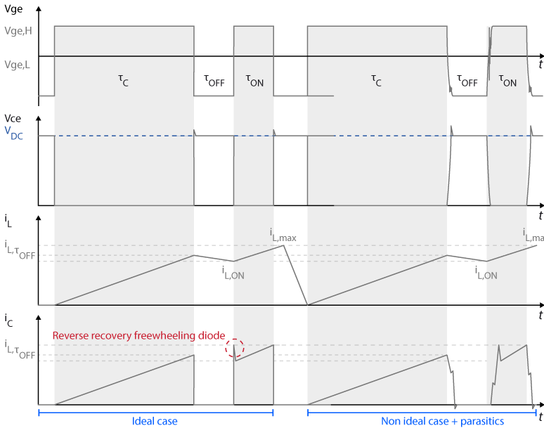
The DPT consists of three phases (a double pulse and a pulse break), as shown in the following figure.
- The first phase is the first pulse phase, with the duration τc (c stands for charging phase)
- The second phase is the pulse break phase, with the duration τoff
- The third phase is the second pulse phase, with the duration τon
By setting the turn-off τoff and turn-on τon timings of the DUT, the turn-on and turn-off behavior can be measured over the full range of operating conditions.
To obtain the desired current at turn-off time, the first pulse duration τc has to be computed as [1]:
$$\tau_{c}=L\cdot\frac{I_{test}}{V_{DC}}$$
where \(L\) is the inductor value, \(I_{test}\) is the desired test current and \(V_{dc}\) is the DC voltage.
Ideally, the turn-off and turn-on measurements must be carried out for the same desired test current value. Unfortunately, during τoff, the current flowing through the antiparallel diode is slightly decreased, due to parasitic series resistances. In light of this, the length of this break is chosen as significantly shorter than τc to keep the current as constant as possible, but still long enough to ensure that the switching process has decayed before the second pulse.
The duration of τon remains significantly shorter than τc to ensure that the current through the DUT does not reach an impermissibly high value. Particular attention must be given to the reverse recovery of the antiparallel diode. The stored charge in the diode adds a current component, resulting in a peak overshoot in the current at the beginning of τon that the switch must handle.
Dimensioning the load inductor
In the design of the circuit parameters, the load inductor and capacitor bank values have priority since they affect the overall performance, stability, and system efficiency. Since the capacitor bank value of the PEB4050 power module is already fixed at 1100µF, the only dimensioning left is for the load inductor.
The load inductor has to be selected to maintain the current as constant as possible between two switching events of the DPT. On the other hand, a large load inductance increases τc with a consequent self-heating of the semiconductor device and the switching characteristics, which are also linked to temperature. In this note, the maximum τc is set as 200µs. The highest load inductor given τc and the test conditions can be derived by as [1]:
$$L\le\tau_{c}\cdot\frac{V_{DC}}{I_{test}}$$
The load inductor must be chosen so that its saturation level is higher than the highest test current.
The effect of parasitics
Parasitic components are present in any real circuit and rise from the setup and different measurement equipment used for carrying out the test. These parasitic components can cause voltage spikes and ringing, with EMI and reliability issues in the worst cases. The authors in [2] present extensive information to understand the impact of parasitics on semiconductor switching behavior with a detailed view of the resulting waveforms.
The effect of parasitic components is the exacerbation of non-ideal behaviors of the switching devices, such as ringing, overshoot, and additional losses. The following figure illustrates the difference between the ideal and the real switching events considering non-idealities and parasitics.
Switching timings
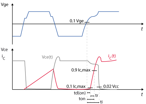
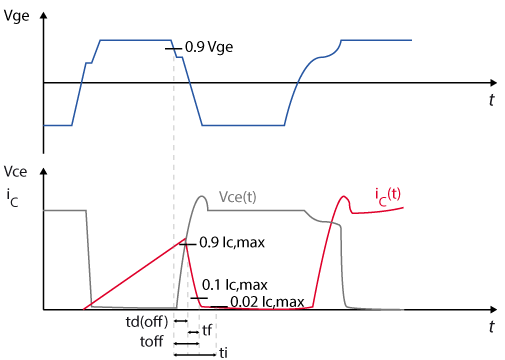
The following figure illustrates the IEC 60747-9 [3] standard to measure IGBT turn-on and turn-off times and switching energies. If the switching behavior of a MOSFET needs to be characterized, please refer to IEC 60747-8 [4].
For turn-on measurements [3]:
- Turn-on delay \(t_{d(on)}\): the time between the 10% of VGE and the 10% of IC,max.
- Turn-on rise time \(t_{r}\): the time between the 10% of IC,max and the 90% of IC,max.
- Turn-on time \(t_{on}\): the sum of \(t_{d(on)}\) and \(t_{r}\).
- Turn-on energy: the time integral of VCE x IC between the 10% of VGE and the 2% of VCC.
For turn-off measurements [3]:
- Turn-off delay \(t_{d(off)}\): the time between the 90% of VGE and the 90% of IC,max.
- Turn-off fall time \(t_{f}\): the time between the 90% of IC,maxand the 10% of IC,max.
- Turn-off time \(t_{off}\): the sum of \(t_{d(off)}\) and \(t_{f}\).
- Turn-off energy: the time integral of of VCE x IC power between the 90% of VGE and the 2% of IC,max.
The turn-on and turn-off energy calculations, which are out of the scope of this article, are further addressed in [3] considering the effect of parasitics.
Software resources for double pulse test
The control model available here after is implemented in Simulink using the imperix ACG SDK blockset. The model can both simulate the ideal behavior of the system in an offline simulation and generate code for real-time execution on the controller of B-Box RCP. The minimum requirements are:
- Imperix ACG SDK (latest version recommended)
- For control code development and simulation in Simulink:
- MATLAB Simulink R2016a or newer
- Simscape Power Systems
On the control side, a finite state machine (FSM) manages the activation and deactivation of PWM outputs. This FSM also includes a counter to prevent the DUT from overheating. Additionally, an Imperix user fault block ensures that the PWM outputs are deactivated if the current exceeds the specified threshold for more than 0.001 seconds.
Experimental setup and results
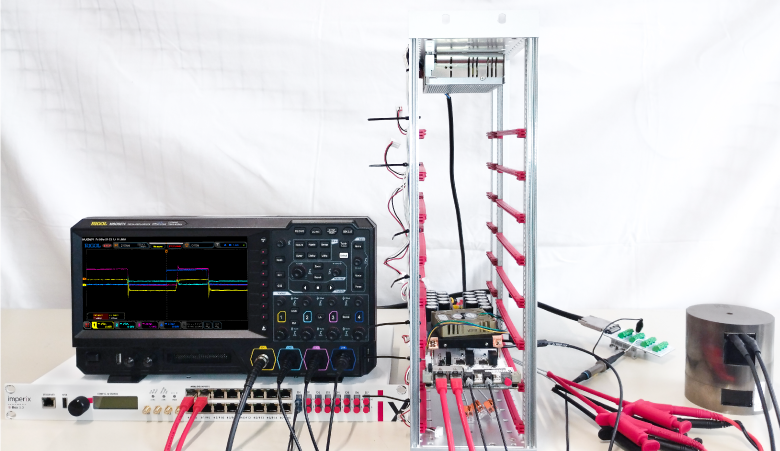
A comprehensive list of the required hardware to carry out the same DPT with imperix products is given in the following:
- 1x Programmable controller (B-Box RCP)
- 1x PEB4050 power module (includes switches, diodes, DC link capacitor, and gate drive circuit)
and additional components :
- 1x Bidirectional DC power supply (400V) rated 6 kW
- 2 x || 0.95 mH inductors (rated 35Arms) with saturation level > 70A.
- 1x Rogowski coil for current measurement (50 MHz bandwidth)
- 2x Voltage probes for voltage measurement (100 MHz bandwidth)
- 1x Oscilloscope
The turn-on and turn-off transitions of the IGBT voltage and current are recorded using a 70 MHz digital oscilloscope. The tests are carried out at four different DC bus voltages, starting from 100V and varied in steps of +100V. The inductor current \(I_{L}\) is varied from 20A to 70A, in steps of 10A.
Measurements tips
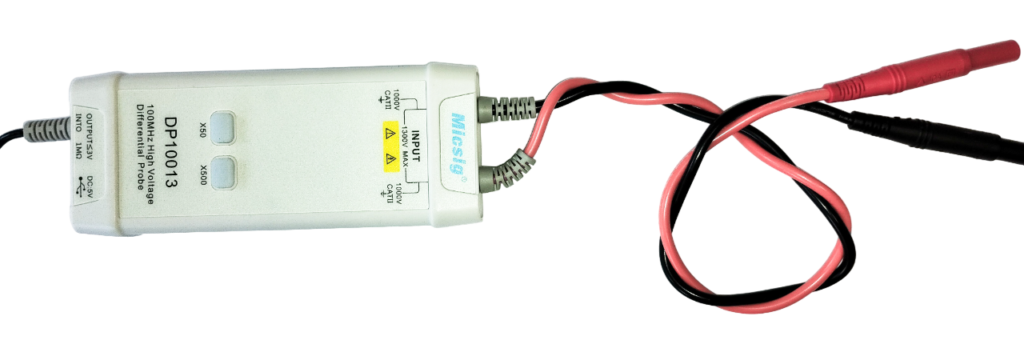
When measuring voltages at non-ground reference potentials, differential probes with a high common mode rejection ratio are essential. This is necessary due to the potential for the DUT to exhibit very high dv/dt levels with respect to the scope ground.
Long leads and pins increase the parasitic inductance, increasing parasitic coupling into the voltage signal. Therefore, to minimize unintended noise coupling and achieve the best measurements, twisting the leads in the lab is advisable, as shown in the following picture.
To measure the switching current, a current sensor must be fitted around the emitter of the DUT, as shown in the following figure.
Test results
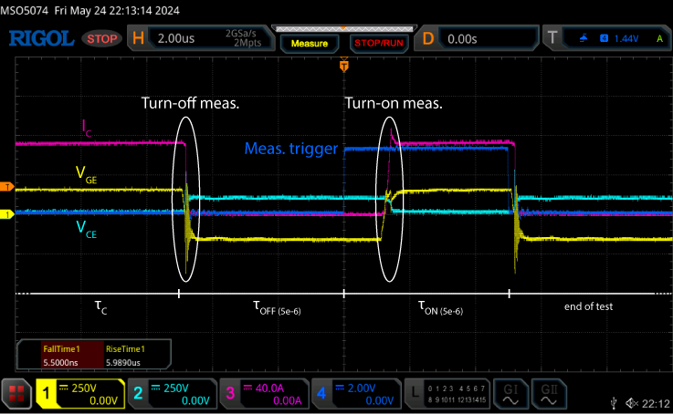
The oscilloscope capture for the 100V – 70A case is shown in the following figure, where the three phases of the double pulse test and the measurement instants are highlighted.
Once the double pulse test is over, the resulting data can be exported and the relative timings can be analytically assessed following the relative IEC standard [3], [4].
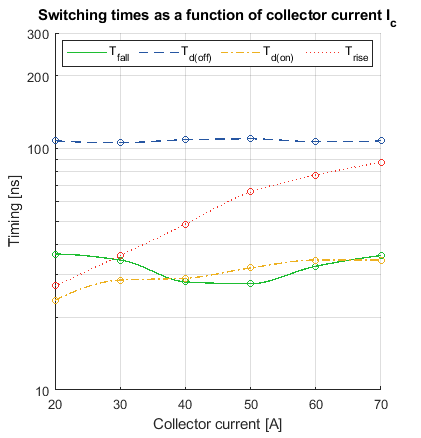
The resulting timings are plotted for every defined voltage level as a function of the collector current and the relative results. Only the 400V timings are shown in the following figure for better readability. Then, the result can be compared to the one given on the manufacturer’s datasheet.
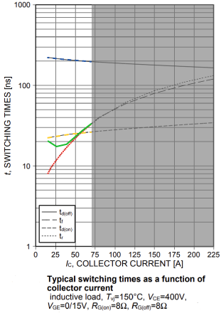
Since the datasheet provides curves at different operating conditions, no straightforward direct comparisons can be made. However, if we look at both results, the \(T_{d(off)}\) and \(T_{d(on)}\) timings trends are consistent with the ones shown in the datasheet. The \(T_{fall}\) time is faster than the one provided in the datasheet. This is justified by the different gate emitter voltage in the PEB 4050 module, driven at +15/-15V instead of 0/+15V. Since the switching speed is influenced by how quickly the gate charge can be moved, the larger voltage swing in the +15/-15V case allows the gate charge to be moved more quickly, reducing the \(T_{fall}\) time. On the other hand, the \(T_{rise}\) time is slower because it takes longer to charge the gate capacitance across the larger voltage swing.
References
[1] Rodhe & Schwarz, “Tips & Tricks on Double-Pulse Testing,” rohde-schwarz.com/us/applications/, Accessed May 2024.
[2] J. Wang, H. S. -h. Chung and R. T. -h. Li, “Characterization and Experimental Assessment of the Effects of Parasitic Elements on the MOSFET Switching Performance,” in IEEE Trans. on Power Electronics, Jan. 2013, doi: 10.1109/TPEL.2012.2195332
[3] IEC 60747-9, “Semiconductor devices – Part 9: Discrete devices – Insulated-gate bipolar transistors (IGBTs)”, Nov. 2019.
[4] IEC 60747-8, “Semiconductor devices – Discrete devices – Part 8: Field-effect transistors”, Dec. 2010, [Consolidated in 2021].


