Table of Contents
This article provides some insights on the computation of optimized switching angles for use with imperix’s PP-PWM modulator. It introduces one possible approach for pre-computing one – or several – Optimized Pulse Patterns (OPPs) that can later be pre-loaded into a digital controller for use during run-time operation.
In this example, Selective Harmonic Elimination (SHE) is used as a modulation technique for a medium-voltage drive. The article focuses on the off-line computation of the optimized switching angles, while more information on the run-time execution is given in TN158.
Numerous techniques exist for solving the optimization problem related to the computation of OPPs [3]. Among them, this article focuses on an algorithm called Particle Swarm Optimization (PSO), mainly for its ability to address any number of switching angles as well as number of output levels.
SHE problem definition
Selective Harmonic Elimination aims to minimize the amplitude of specific current harmonics. Relying on the sinewave’s quarter-wave symmetry assumption, \(N\) harmonics can theoretically be eliminated using \(N\) optimized switching angles. To do so, the problem can be formulated by considering the Fourier series expansion of the inverter output voltage with the assumption of \(2\pi\) periodicity [1].
$$u(\theta) = \frac{a_0}{2} + \sum_{n=1}^{\infty} (a_n\cos(n\theta) + b_n\sin(n\theta))$$
with the Fourier coefficients:
$$a_n = \frac{1}{\pi}\int_{0}^{2\pi} u(\theta)\sin(n\theta)\mathop{}\!\mathrm{d}\theta$$
$$b_n = \frac{1}{\pi}\int_{0}^{2\pi} u(\theta)\cos(n\theta)\mathop{}\!\mathrm{d}\theta$$
The amplitude of the nth harmonic in the PWM switching signal can then be expressed as:
$$ \hat{u}_n = \sqrt{a_n^2 + b_n^2}$$
From here, considerations such as half-wave or quarter-wave symmetry of the sinewave can be taken into account to simplify the problem definition. These assumptions will however limit the search space available to find the optimum solution, which may lead, in some cases, to a suboptimal switching pattern [3].
Imposing the quarter-wave symmetry, meaning that \(u(\pi + \theta) = -u(\theta)\), eliminates all even harmonics and the DC component, and also implies the following condition on the switching angles:
$$ 0 \leq \alpha_1 \leq \alpha_2 \leq … \leq \alpha_N \leq \frac{\pi}{2}$$
The amplitude of the nth harmonic component in the output voltage then becomes \(\hat{u}_n = |b_n|\). Also, \(b_n\) can be rewritten as:
$$ b_n = \frac{4}{n\pi} \sum_{i = 1}^{N} \Delta u_i \cos(n\alpha_i)$$
where \(\Delta u_i \in\{-1,1\}\) is the switching transition at the corresponding angle [2]. Note that, for a 3-phase inverter with a floating star point, and the quarter-wave symmetry hypothesis, the second and third-order harmonics are, by nature, eliminated.
Subsequently, the objective function can be elaborated such that the amplitude of the fundamental is as close as possible to the desired one and the sum of the unwanted harmonics is minimized:
$$ J_{opt}(\alpha_i, M) = (b_1 – M)^2 + \sum_{n=5,7,11,…}b_n^2$$
where \(M\) is the modulation index and \(b_n\) as defined above.
Obviously, other objective functions could be formulated with the same general idea, but a more subtle implementation. For instance, weighting factors could be used, or different objectives (other than the elimination of specific harmonics) can also be included.
Particle Swarm Optimization
Particle Swarm Optimization (PSO) is a bio-inspired optimization method suitable for non-convex problems under constraints, such as the computation of optimized pulse patterns.
The main idea behind PSO is to move a set of candidate solutions, that can be seen as particles, in a search space defined by a cost function [4]. The movement of the particles is determined by their local best position but also by the overall best-known position in the search space. This results in a swarm of particles moving toward the solution that minimizes/maximizes the cost function.
This method does not always guarantee convergence towards a global minimum and may not even converge depending on the particles’ initial conditions and parameters. However, the more particles, the better the chances of converging towards the global minimum. Therefore, in the following script, it is assumed that the number of particles is high enough so that it converges toward the global minimum.
Computation of optimized switching angles using Matlab
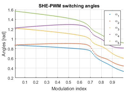
A Matlab script (SHE_OPT.m) for the offline computation of optimized switching angles is given below and is used to compute 5 angles for a three-level three-phase inverter.
In this script, the objective is to minimize the following cost function:
$$ J_{opt}(\alpha_i, M) = (b_1 – M)^2 + \sum_{n=5,7,11,…}b_n^2$$
where \(M\) is the modulation index. Note that the equation for \(b_n\) is mentioned above.
Minimizing this cost function will return the optimal switching angles for a given modulation index \(M\). This process will then be repeated for each desired modulation index.
The required parameters for the script are:
- the number of voltage levels (in the output voltage).
- the number of switching angles (per quarter-wave).
- the number of phases (1 or 3).
- the modulation index increment (which will define a vector of modulation index for which the angles will be optimized).
Other parameters related to the PSO are also available such as the minimization tolerance, the maximum number of iterations, the number of particles, …
The following plot shows the resulting optimized switching angles for the three-level inverter.
This angles optimization method has been used for a 3-level NPC inverter, with 3 switching angles per quarter period, in Selective Harmonic Elimination applied to medium voltage drives.
References
[1] H. S. Patel and R. G. Hoft, “Generalized Techniques of Harmonic Elimination and Voltage Control in Thyristor Inverters: Part I” in IEEE Transactions on Industry Applications, May 1973, DOI: 10.1109/TIA.1973.349908. Link on IEEE Xplore.
[2] A. Birth, T. Geyer, H. d. T. Mouton and M. Dorfling, “Generalized Three-Level Optimal Pulse Patterns With Lower Harmonic Distortion,” in IEEE Transactions on Power Electronics, June 2020, DOI: 10.1109/TPEL.2019.2953819. Link on IEEE Xplore.
[3] M. S. A. Dahidah, G. Konstantinou and V. G. Agelidis, “A Review of Multilevel Selective Harmonic Elimination PWM: Formulations, Solving Algorithms, Implementation and Applications,” in IEEE Transactions on Power Electronics, Aug. 2015, DOI: 10.1109/TPEL.2014.2355226. Link on IEEE Xplore.
[4] J. Kennedy and R. Eberhart, “Particle swarm optimization,” Proceedings of ICNN’95 – International Conference on Neural Networks, 1995, DOI: 10.1109/ICNN.1995.488968. Link on IEEE Xplore.
[5] Wikipedia: Particle swarm optimization


