Table of Contents
This technical note provides a short overview of the key factors that are essential when designing a resonant tank circuit for an LLC converter. By reading this article, a sufficient understanding of the main factors impacting the design can be gained, such that the right questions can be raised when referring to more detailed references such as [1], [2], and [3].
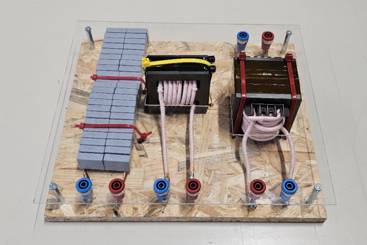
In a second step, the provided information is illustrated with the design of a real-world resonant tank circuit, successfully integrated into the demonstrations for TN125, TN126, & AN010.

Resonant tank circuit parameter selection
The resonant tank of an LLC series resonant converter is composed of the following three elements:
- Resonant capacitor
- Resonant inductor
- Magnetising inductor
These three elements, along with the load that the LLC converter will be driving, define the operating area of the LLC converter and its ability to change the gain of the converter during operation.
When designing the resonant tank circuit of the LLC converter, it is important to start from the constraints. Typical constraints include:
- The switching frequency range set for the converter (this arises from converter size and efficiency requirements and switch technology selected).
- The desired range of possible voltage gains.
Case I: resistive load
The resistive load case is often used as a starting point in research applications. It is described in TN125. It is a good starting point, which is widely documented in the literature.
There are three separate optimizable criteria when selecting the parameters of the resonant tank:
- \(f_r = \frac{1}{2 \pi \sqrt{L_r C_r}}\)
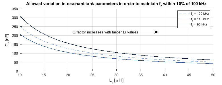
The values of \(L_r\) and \(C_r\) will select the resonant frequency of the LLC converter. As the converter will operate close to the resonant frequency, it is a decent approximation to assume that the switching frequency is approximately equal to the resonant frequency. The figure below shows how much variation can be allowed in the resonant tank circuit parameter values before the resonant frequency shifts beyond the arbitrarily chosen 10% tolerance. The actual acceptable tolerance will depend on the specific application.

- \(Q = \displaystyle \frac{\sqrt{\frac{L_r}{C_r}}}{R_{ac}}\)
The quality factor (Q) is the ratio of the load impedance referred to the primary and \(\sqrt{\frac{L_r}{C_r}}\), which is a parameter describing the impedance of the resonant tank circuit.
A high quality factor describes an LLC converter whose resonant tank circuit impedance is comparatively larger than the referred load impedance. As such, a converter with a higher Q would have lower circulating currents and possibly be more efficient than its low Q counterpart. On the other hand, a low Q allows for higher boost operation, which may be necessary due to external constraints.
- \(L_n = \frac{L_m}{L_r}\)
\(L_n\) is the ratio between the magnetizing inductance and the resonant inductance. As seen in TN125, the ratio between the two inductances affects the gain of the resonant tank circuit.
Increasing the value of \(L_m\) (and \(L_n\) as a result) is desirable as the magnetizing current of the transformer is inversely proportional to the value of the magnetizing inductance. However, a converter with a large \(L_n\) requires a larger deviation in frequency to achieve a given gain during operation compared to a converter with a smaller \(L_n\).
As will be discussed in the transformer design section, a large deviation in switching frequency can have a negative impact on the frequency-dependent core and winding losses.
Multiple references suggest that selecting \(L_n \approx 6\) is a good compromise between the controllability of the LLC converter and the efficiency of the magnetics [4, 5].
Due to practical sizing limitations, the values of the resonant tank parameters are often limited. As a result, higher resonant frequencies are favored such that the circulating current in the resonant tank is minimized.
Case II: battery load
LLC converters are often used in battery charger applications, in which case the load cannot be described as a constant resistance, but rather a constant voltage. This case is described in TN126.
Given that the battery voltage is only weakly dependent on its current, the gain of the LLC converter can be considered to be externally fixed. As such, the design procedure of the resonant tank circuit must be adapted. The main challenge, in this case, is to ensure that the maximum charge power can be attained for all loading conditions.
Ensuring that the resonant tank can meet the required gains in all conditions is an iterative process, because the following constraints have to be accounted for when designing the tank circuit:
- Only an integer number of turns is possible in the magnetics design.
- Only a limited set of magnetic cores is available unless custom magnetics are developed.
- Only a limited set of capacitor values is available to build up the capacitor bank.
N.B.: While these constraints apply to case I as well, the latter is comparatively simpler, thanks to the fact that the fixed resistance condition imposes the study of one operating point only.
Transformer design
The transformer provides the isolation between the primary and secondary, as well as a second inductance in series with the resonant inductor and capacitor. It is recommended to address its design first, so that the resonant inductor and resonant capacitor can be designed second. The latter can then be possibly adjusted based on the obtained transformer.
High-frequency transformer cores, such as what would be present in an LLC converter, are often not saturation-limited, but limited by the core losses. Therefore the design procedure involves the minimization of the flux density within the transformer core.
The current that creates the flux in the transformer, and therefore the core losses, is the magnetizing current.
\(B \propto N\) and \(B \propto \frac{1}{\Re}\)
\(L_m \propto N^2\) and \(L_m \propto \frac{1}{\Re}\)
Since \(B\) is proportional to the number of turns, but \(L_m\) is proportional to the number of turns squared, the magnetizing inductance of the transformer for a given flux density can be increased by increasing the number of turns in the windings and increasing the reluctance (via the airgap).
The magnetizing inductance is generally tuned by changing the number of turns in the transformer windings and the air gap thickness. As these parameters are adapted, the core size must also be varied to accommodate the windings in the window area and to ensure that the cross-sectional area is sufficient to keep the value of \(B\) low.
Core material selection
Multiple different core materials can be chosen for the transformer. In the 10s of kHz to 10s of MHz range, ferrites tend to have the best performance. Even so, manufacturers produce different materials, which are optimized for different frequency ranges [6]. It is important to pick the correct material since the core losses in ferrite core materials also follow an exponential scale with frequency. If the required deviation in frequency crosses the boundaries suggested by core manufacturers, optimizing the core selection for overall efficiency will become more challenging.
Winding wire selection
The wire selection for the transformer windings is an exercise in maximizing the window area utilization of the transformer core. The severity of the skin effect, the proximity effect, and other parasitic effects dictate what is the effective proportion of the copper cross-sectional area. The table below provides a suggestion for wire selection when winding a high-frequency transformer.
| \(f_r < 20 kHz\) | \(f_r < 1 MHz\) | \(f_r > 1 MHz\) |
|---|---|---|
| Standard wire | Litz wire | Other solutions |
| Litz wire unnecessarily takes up more of the window area | The thinner strands of wire offset the increased AC resistance due to the skin effect | The parasitics involved in the construction of Litz wire become non-negligible at this frequency [7] |
The recommended typical current density in such a transformer is 6-10A/mm2. The lower part of that range leads to fewer losses, and hence a temperature rise that is comparatively more easily manageable.
When winding the transformer, it is good practice to keep the windings away from the added air gap in the transformer to limit the fringing losses from the leaking magnetic field.
Resonant inductor design
Assuming that the resonant inductor is not integrated into the transformer – which is a design technique beyond the scope of this article – a similar optimization to the transformer must also take place for the resonant inductor.
Unlike the transformer, the entire resonant tank current is responsible for the flux density in the core of the inductor since there is no induced current to cancel out the flux generated by the load current. Therefore, compared to the transformer, the air gap must be larger since the reluctance of the inductor needs to be larger to minimize the flux density in the inductor core.
Resonant capacitor design
The resonant capacitor must fulfill the following two criteria, including any temperature and voltage derating.
- The capacitor must be able to withstand the maximum peak voltage across it the whole range of operation. Due to resonance, this peak can be significantly higher than the input voltage.
- The capacitor must be able to withstand the peak & RMS current that the resonant tank circuit will impose during the operation of the LLC converter.
Given these two factors, a single capacitor is usually insufficient and as such, a capacitor bank must be made.
Importantly, as the first harmonic approximation (FHA) gives only a poor approximation of the actual magnitude of the voltage and current across the resonant capacitor, simulation is recommended for sizing the capacitor bank.
Example design
The resonant tank circuit in this section is designed to be flexible enough to be used in TN125 and TN126. Nonetheless, since the requirements are more strict for TN126, the constraints are based on the latter, namely:
- \(P_{max}\) = 3.5 kW
- \(V_{in}\) = 340 V
- \(V_{out}\) = 325 V – 440 V
- Desired \(f_r\) = 100 kHz
Resonant tank circuit design process
The first step is to fix the switching frequency to the constraint and find the maximum \(L_m\) for a given \(L_n\) ratio, while still meeting the gain constraint at maximum power, which is the most demanding load.
Following these iterations, a range of possible \(L_m\) values that allow the resonant tank circuit to meet the gain criteria can be found. Then, \(L_r\) can be calculated from the selected \(L_n\) ratio, and \(C_r\) can be calculated using \(L_r\) and the desired \(f_r\).
In this example, to adhere to a resonant frequency of 100 kHz, an \(L_m\) range from 51 µH to 130 µH provides the possibility of having an LLC converter that can meet the gain criteria. It is assumed that the transformer would have a turns ratio \(n\) of close to 1, to facilitate the hand winding of the transformer.
Subsequently, by an iterative process, a transformer design is made that would meet the above requirements while minimizing core losses.
Once a satisfactory design is found, the next step is to build the transformer. Due to non-idealities, and tolerances in the airgap length, the actual value of \(L_m\) of the transformer may differ considerably from the original design. In this example, the transformer was wound with an 8/9:1 turns ratio with an \(L_m\) of 90 µH (measured on the primary winding).
Subsequently, after having characterized the transformer to ensure that the resonant tank circuit has a \(L_n\) close to the desired value, the resonant inductor can be implemented. Due to the integer number of turns and the variance in the air gap, this value will nevertheless vary. In this example, the total resonant inductance ended up being 21 µH.
Since the resonant capacitance is the easiest to finely tune, assembling the resonant capacitor is the final step in the resonant tank circuit design process. In this example, a 110 nF capacitor bank was made with 5 nF legs such that the resonant frequency is approximately 100 kHz, while ensuring the current in each capacitor is below the desired threshold.
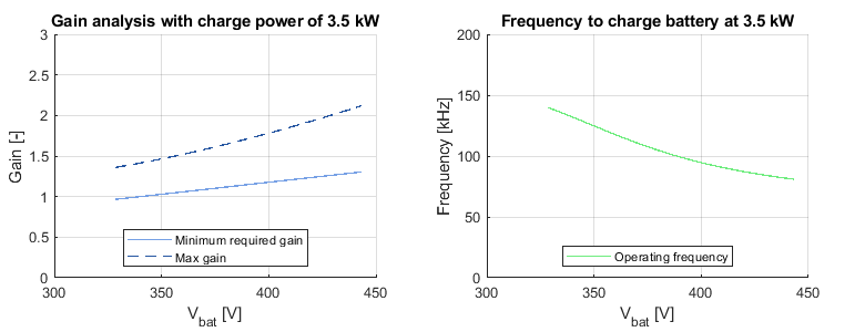
Figure 3 demonstrates that the iterative process resulted in a resonant tank meeting the desired criteria.

In summary, the final parameters for the resonant tank are:
- n = 8/9
- \(L_m\) = 90 µH
- \(L_r\) = 21 µH
- \(C_r\) = 110 nH
References
[1] C. Adragna, LLC Resonant Converters: An Overview of Modeling, Control and Design Methods and Challenges , now, 2022.
[2] H. Huang, “Designing an LLC Resonant Half-Bridge Power Converter”, Texas Instruments, 2010
[3] Y. Wei, Q. Luo, Z. Wang and H. A. Mantooth, “A Complete Step-by-Step Optimal Design for LLC Resonant Converter,” in IEEE Transactions on Power Electronics, April 2021
[4] S. Abdel-Rahman, “Resonant LLC Converter: Operation and Design”, Infineon Technologies North America, 2012
[5] B. Yang, “Topology Investigation for Front End DC/DC Power Conversion for Distributed Power System” – Chapter 4, PhD Thesis, Virginia Tech, 2003
[6] TDK Electronics AG “Product catalog: Ferrite Materials,” https://www.tdk-electronics.tdk.com/en/529404/products/product-catalog/ferrites-and-accessories/ferrite-materials (accessed Mar. 8, 2024).
[7] F. Terman, Radio Engineers’ Handbook. McGraw-Hill, London, 1950.


