Table of Contents
This note introduces the virtual impedance method for power decoupling in resistive lines. An implementation example is provided to validate the virtual impedance method with droop control featuring the programmable inverter TPI 8032 and ACG SDK.
An overview of the hardware architecture and detailed instructions on how to program the device are addressed in getting started with the TPI 8032.
Power coupling issue in resistive lines
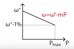
Droop control is a well-established communication-less control strategy for regulating the power-sharing between Grid-Forming Inverters (GFMI). However, the idea of droop control is based on the fact that the active and reactive power flow can be decoupled in an inductive transmission line, which is not always true, especially in low-voltage transmission grids.
Considering the single-phase equivalent circuit for the symmetrical three-phase transmission line, the active and reactive power flow in a transmission line can be calculated by:
$$ P=3\cfrac{V_1}{R_{l}^2+X_{l}^2}[ R_{l}(V_1-V_2\cos\delta)+X_{l}V_2\sin\delta] $$
$$ Q=3\cfrac{V_1}{R_{l}^2+X_{l}^2}[ X_{l}(V_1-V_2\cos\delta)-R_{l}V_2\sin\delta] $$
When the transmission line is mostly inductive (\(R_l\approx 0\)), and the phase angle is small enough (\(\sin(\delta)\approx \delta, \cos(\delta)\approx 1\)), the active power \(P\) and reactive power \(Q\) can be further simplified as [1]:
$$ P\approx3\cfrac{V_1V_2}{X_{l}} \delta $$
$$ Q\approx3\cfrac{V_1(V_1-V_2)}{X_{l}} $$
Based on the equations above, the active and reactive power flows can be fully decoupled and controlled independently. However, if the transmission line is mostly resistive (\(R_l \ne 0\)), the above approximations no longer hold, and both active and reactive power depend on the angle and the voltage variation along the line.
Considering a similar setup as introduced in Parallel operation of GFMIs, two GFMIs running in parallel are considered with a load, connected at the other end of a mainly resistive line. With conventional droop control, a load step \(\Delta P_{\text{load}}\) determines a variation of the frequency reference \(\omega^*\). But with a resistive load, the reactive power \(Q\) is also affected, causing the change of the voltage reference \(V^*\). Again, since the active power \(P\) also depends on the voltage, \(P\) will change further, leading to oscillations and possible instability of the system.
Working principle of the virtual impedance method
To avoid the coupling issue between active and reactive power, a virtual impedance can be added to the conventional droop control. The working principle of the virtual impedance method is to mimic a line inductance by subtracting the voltage reference \(V^*\) by a virtual voltage drop \(V_{\text{v}}\).
$$ V_{\text{v}} = L_{\text{v}}\frac{\mathrm{d} I}{\mathrm{d} t} $$
Where \( L_{\text{v}} \) is the virtual inductance.
To avoid the unwanted noise amplification of numerical derivation, approximation methods have been proposed in [2] by calculating the virtual voltage drop in the rotating reference frame (dq0):
$$ V_{\text{v},d} = -L_{\text{v}}\omega I_{q} $$
$$ V_{\text{v},q} = L_{\text{v}}\omega I_{d} $$
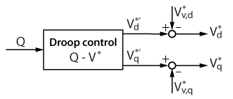
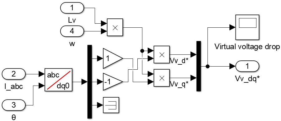
The corresponding control diagram is as follows:
In contrast to a conventional droop control, an active power variation determines a voltage reference variation through a virtual inductance. Moreover, the virtual voltage drop allows the conceptual decoupling of active and reactive power. Therefore, stability is ensured by using the droop control with virtual inductance. The effect of the \(L_{\text{v}}\) value is studied in the experimental result section.
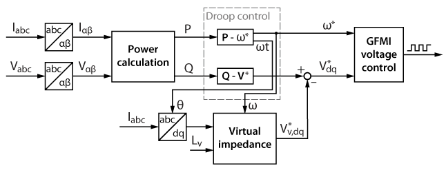
With the addition of the virtual impedance, the whole diagram of the droop controller becomes:
Virtual impedance implementation with imperix ACG SDK
The control models available here after are implemented in Simulink using the imperix ACG SDK blockset. The models can both simulate the behavior of the system in an offline simulation and generate code for real-time execution on the TPI 8032. An introductory guide regarding the TPI is addressed in Getting started with the TPI 8032. To run these models, the minimum requirements are:
- Imperix ACG SDK 2024.2 or newer.
- MATLAB Simulink R2016a or newer.
- For simulation only: Simscape Electrical
The Simulink implementation of the virtual impedance is shown below.
Experimental setup
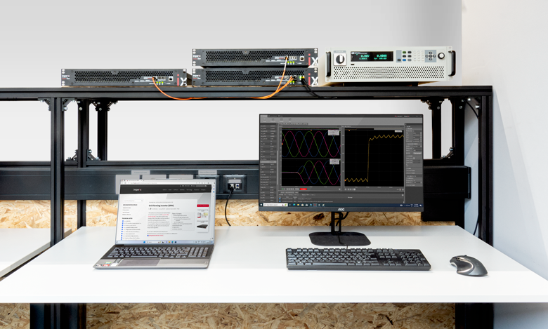
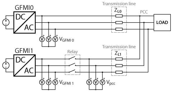
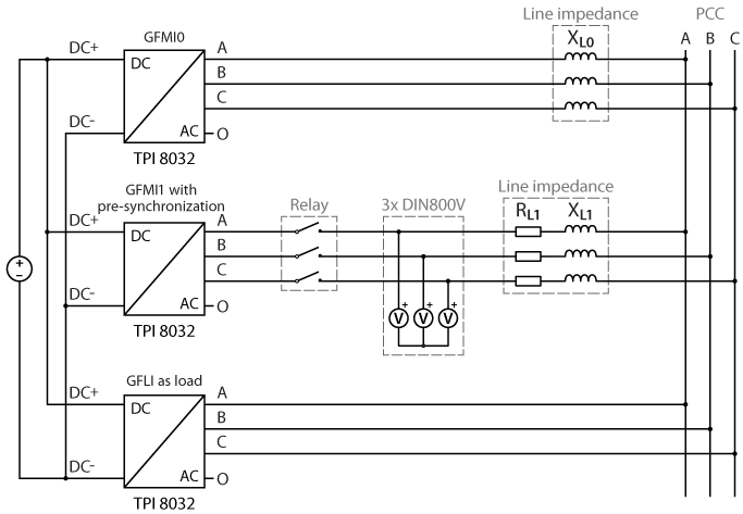
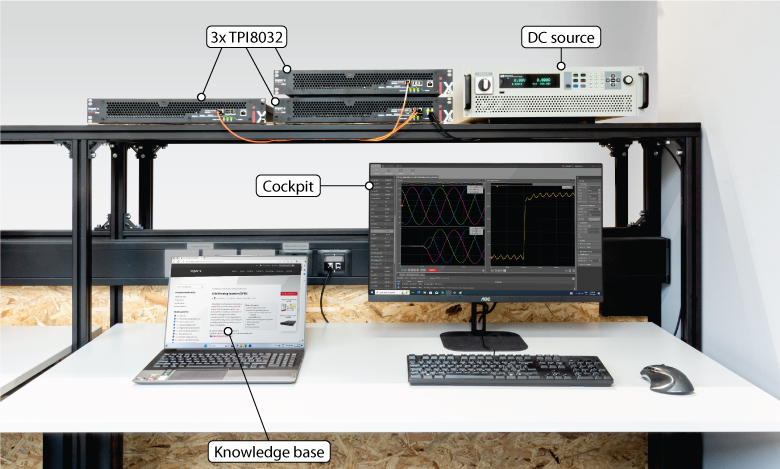
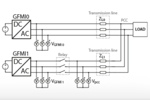
The experimental validation of the virtual impedance method is carried out with a similar setup as in Parallel operation of GFMIs with two TPIs running in parallel as GFMIs and one TPI as GFLI as an active load. The three TPIs are used in a master-slave configuration (connected with SFP cables), meaning that they are programmed from the same Simulink model. The GFMI0 is connected to the PCC through inductors emulating an inductive transmission line, while the GFMI1 is connected through resistors and small inductors emulating a resistive transmission line. A relay controlled by a GPO port is used to connect GFMI1.
The required equipments are:
- 3x TPI 8032 three-phase inverter
- ACG SDK toolbox for automated generation of the controller code from Simulink or PLECS
- 1x bidirectional DC power supply (800V)
- 6x inductors (3x 2.2mH and 3x 90µH)
- 3x resistors (here 1.6Ω)
- 1x three-phase relay
- All the necessary cables
The following table summarizes the operating conditions:
| Parameter | Value |
|---|---|
| Control and switching frequency | 50 kHz |
| Maximum active power P Maximum apparent power S Maximum reactive power Q | 16 kW 22 kVA 15.1 kVar |
| Grid Voltage DC voltage Maximum RoCoF \(\rho\) | 400 VRMS 800 V 1 Hz/s |
| \(\Delta f\) (1%) \(\Delta V\) (10%) | 3.14 rad/s 32.5 V |
| Line inductance of GFMI0 Line resistance of GFMI1 Line inductance of GFMI1 | 2.2 mH 1.6 Ω 90 µH |
| APC droop coefficient \(m\) APC – LPF cut-off frequency APC – HPF cut-off frequency RPC droop coefficient \(n\) RPC – LPF cut-off frequency | 1.9635e-04 0.3 Hz 0.1 Hz 0.0022 0.3 Hz |
Based on typical line parameters taken from [3], the resistance and reactance of PVC-insulated multi-core copper conductor with a cross-sectional area of 4mm2 are:
$$ R_l = 5.8783 \quad \Omega/\text{km} $$
$$ X_l \space @\, 60 \text{Hz} = 0.113 \quad \Omega/\text{km} $$
The lumped components used experimentally are approximately equivalent to a transmission line of 300m, which is realistic in a small low-voltage system.
Experimental results
The experiment is performed by running GFMI0 while GFMI1 is still unconnected. Then, GFMI1 is connected with prior pre-synchronization. As the first step, no virtual impedance is implemented on GFMI1. The active and reactive power flow after GFMI1 is connected are shown below. The experiment has to be stopped after 42 seconds to avoid excessive current.
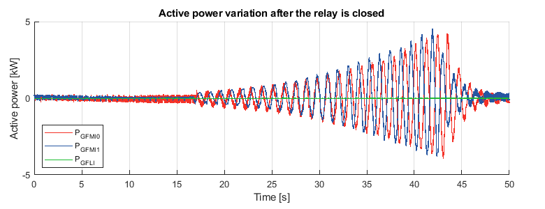
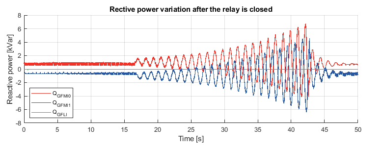
Without the virtual impedance, oscillations of power exchange between the two GFMIs can be observed, leading to instability of the system.
After adding the virtual impedance to GFMI1, the system’s stability can be ensured. To study the effect of different virtual inductance values, an active power step of 15kW is performed on the load under different virtual inductance values.
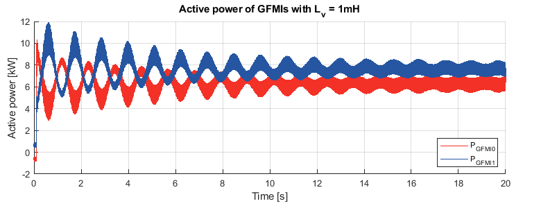
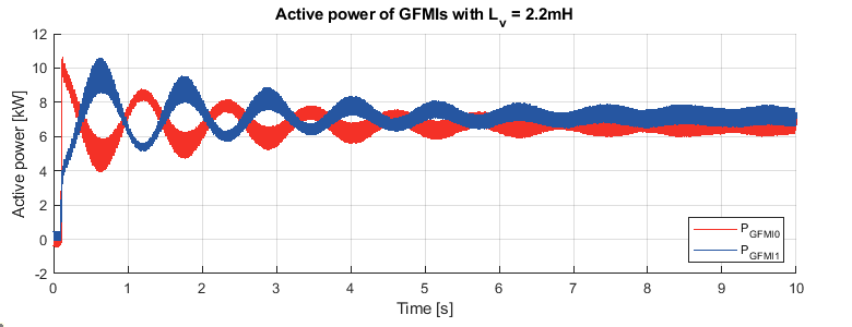
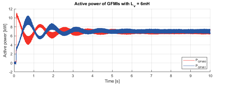
It can be observed from the results that for smaller virtual inductance value \(L_{\text{v}} = 1\,\text{mH}, X_l/R_l = 0.2 \), the effect of the line resistance cannot be fully eliminated. Oscillations happen when the load changes and still exists in the steady state. Besides, an inaccuracy of active power sharing can be observed. As the virtual inductance value increases, the effect of the line resistance gets mitigated. For large virtual inductance \(L_{\text{v}}= 6\,\text{mH}, X_l/R_l = 1.17 \), the oscillation in the steady state can be almost removed, and accurate active power sharing can be ensured. Obviously, the virtual inductance cannot be increased infinitely, since the induced virtual voltage drop along the line will cause the PCC voltage to decrease.
To go further
To address the lack of explicit inertia in the control, the inertial characteristics of synchronous generators can be emulated through a virtual synchronous generator control. This is addressed in Virtual synchronous generator.
Academic reference
[1] K. De Brabandere, B. Bolsens, J. Van den Keybus, A. Woyte, J. Driesen and R. Belmans, “A Voltage and Frequency Droop Control Method for Parallel Inverters,” in IEEE Transactions on Power Electronics, Jul. 2007
[2] Y. W. Li and C.-N. Kao, “An accurate power control strategy for power-electronics-interfaced distributed generation units operating in a low-voltage multibus microgrid,” in IEEE Transactions on Power Electronics, Dec. 2009.
[3] Alfanar, “Low voltage power and control cables,” https://www.alfanar.com/catalogs/cables_wires/LV_power_cables.pdf, Accessed Mar. 2024.


