Table of Contents
This technical note demonstrates the control of a Doubly-Fed Induction Generator (DFIG) in a wind turbine application. Firstly, the operating principles and control strategy for a grid-tied DFIG are discussed. A 2MW DFIG is then modeled in an RT-Box to demonstrate how the B-Box RCP can be used in conjunction with a HIL simulator to control complex systems.
DFIG versus SCIM for wind turbine applications
The doubly-fed induction generator (DFIG) is an improvement over its predecessor, the squirrel cage induction machine (SCIM), for generator use cases. It is particularly suitable for cases where the generator speed and torque must be flexible, such as wind turbines.
By comparing the SCIM to the DFIG, the overall benefit of selecting the DFIG can be further analyzed.
Since the slip is not controllable in SCIMs, there are a couple of methods to maximize the generated power in a SCIM-based wind turbine:
- control the rotor using only the blade pitch (slow) and a gearbox given that the SCIM is grid-connected;
- utilize a variable frequency drive to control the stator voltage and process 100% of the generated power through the converter.
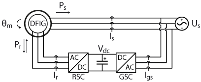
On the other hand, as the DFIG has accessible rotor windings, slip can be controlled by controlling the rotor currents, and the slip is no longer dependent on the turbine operating conditions. As a result of the accessible rotor windings, the DFIG can be controlled using the topology shown in Figure 1 [1].
The topology shown in Figure 1 possesses the following additional advantages:
- assuming small values of slip, the rotor power, and therefore the converter power rating, is a small percentage of the total generated power;
- fluctuations in wind speed can be dealt with using fast rotor current control, bypassing the need for a comparatively inefficient multi-ratio gearbox;
- the controllable slip allows performing MPPT for maximum power generation electrically instead of mechanically.
The control of the grid-side converter (GSC), and the rotor-side converter (RSC) in Figure 1 is discussed in detail in section 3 of this article.
DFIG operating principle
The rotor speed in a DFIG, operated according to the topology shown in Figure 1, is controlled using the rotor current. Similarly to the induced rotor currents in a SCIM, the rotor currents in the DFIG are synchronized to the slip angle \(\theta_{slip} \). Therefore, the control of the rotor currents can be done by orienting the control to \(\omega_{slip} \). [1]
$$ \omega_{slip} = \omega_{stator} – p \; \omega_m$$
Since the rotor currents can be manipulated by the RSC, increasing or decreasing rotor current allows for the control of the rotor magnetic field strength. This manipulation allows the DFIG to change the speed of the rotor with respect to the stator frequency. As referred to before, this ratio is referred to as slip and can be calculated in the following manner : [1]
$$ s = \frac{\omega_{slip}}{\omega_{stator}}$$
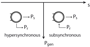
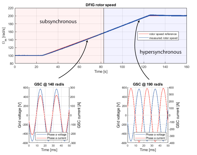
Since the rotor speed can be changed using the rotor current, the DFIG can operate both subsynchronously and hypersynchronously. Figure 2 illustrates the two modes of operation and whether the rotor is consuming or generating active power depending on the mode of operation. [1]
Following that, the stator power in a DFIG is a function of the applied mechanical power and the slip of the generator.
$$ P_s = \frac{P_m}{1-s} $$
Additionally, the power split between the rotor and stator of the DFIG is also a function of slip,
$$ P_r = -s P_s ,$$
hence the requirement of limiting the value of slip to remain within the rated specifications of the rotor speed controller.
DFIG power versus rotor speed
A wind turbine has a torque characteristic which is a function of the windspeed and the rotor speed. Therefore, there is an optimum rotor speed setpoint for a given wind speed. In order to model these effects, a rotor speed/torque look-up table was implemented for this article.
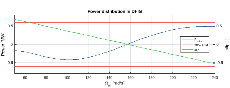
Figure 15 shows the rotor and stator power vary according to the rotor speed/slip for the assumed windspeed. The peak mechanical power is generated at 180 rad/s.
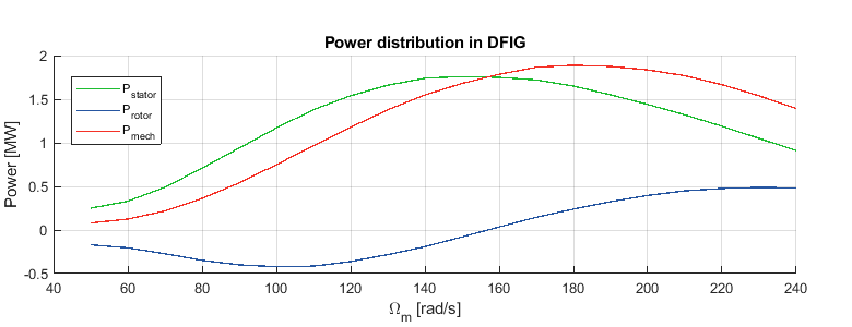
Furthermore, Figure 16 shows that, with the applied torque profile, the (absolute) RSC power remains below 30% of full-scale power and that the DFIG can operate subsynchronously and hypersynchronously.
Control implementation for DFIG in wind turbine applications
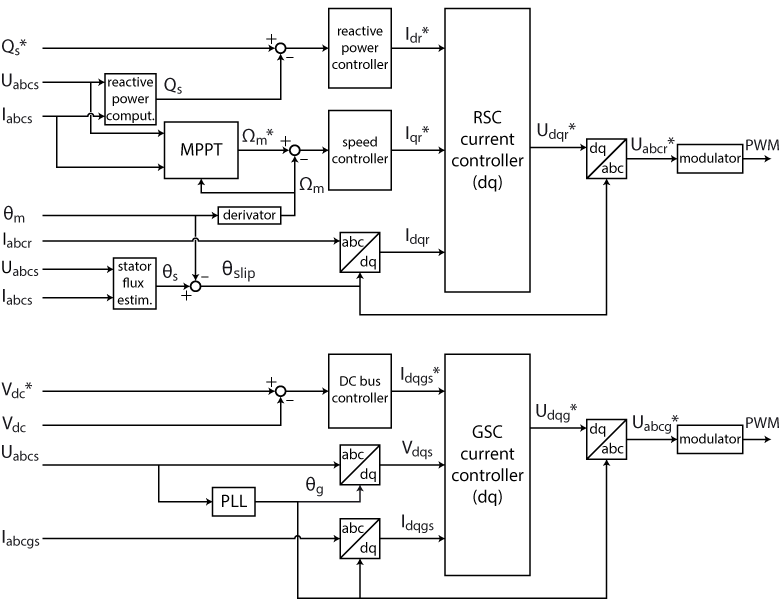
The following sections discuss specific parts of the overall control (Figure 7) in further detail.
Control of the GSC
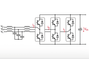
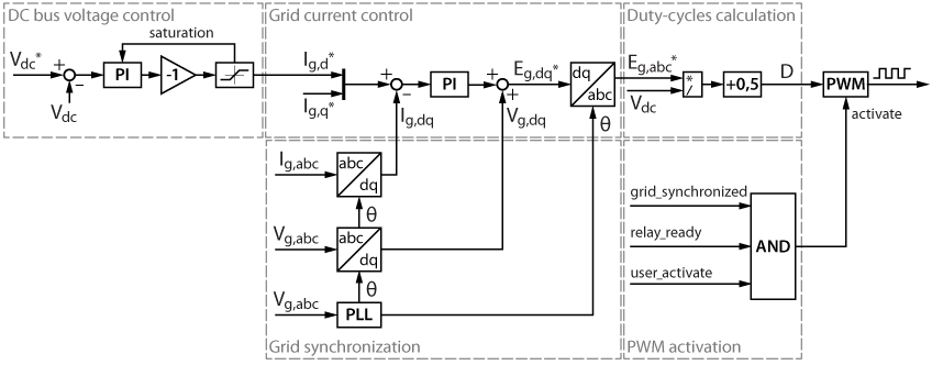
The GSC in a DFIG drive is analogous to an active front-end (AFE). It minimizes the reactive power consumed/generated by the rotor and ensures the DC bus voltage is high enough to allow for the RSC to function. Given that, Figure 3 shows the control of an AFE.
TN166 – Active Front End elaborates further on the control scheme implemented for this converter.
Control of the RSC
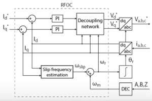
The goal of the RSC is to manipulate the rotor field in order to control the DFIG, similar to TN139 – Rotor Field-Oriented Control (RFOC) of an induction machine. The key difference is that the rotor field in a DFIG can be directly controlled, whereas in a SCIM, the rotor flux is controlled indirectly through stator currents.
Independent power control of a DFIG, connected as shown in Figure 1, is achievable because the active and reactive powers have the following relationship with the rotor current: [1]
$$ P = – \frac{3}{2} \frac{L_m}{L_s} \hat{U}_g (1-s) I_{qr} $$
$$ Q = \frac{3}{2} \frac{\hat{U}_g}{L_s} \left( \frac{\hat{U}_g}{\omega_s} – L_m I_{dr} \right) $$
Inner current loop
To measure/calculate \(I_{qr}\) and \(I_{dr}\), the RSC voltages and currents must be transformed into the slip-oriented reference frame. This is done by performing a Park transform on the measured values. The reference frame is synchronized with \(\theta_{slip} \; = \theta_{stator} – \theta_m\). While \(\theta_{stator}\) can be measured using a PLL on the grid voltage, \(\theta_m\) must either be physically measured, or estimated using an observer.
Since the rotor windings may have a different number of turns compared to the stator, all values are referred to the stator, considering the transformation ratio u.
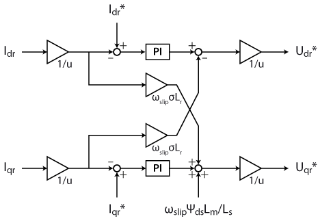
Having calculated \(I_{dqr}\), the rotor currents can then be controlled using PI controllers (shown in Figure 4).
Similarly to the RFOC of SQIM, the transient performance of the PI current controllers in Figure 4 can be improved by including \(I_{qr}\) and \(I_{dr}\) decoupling terms. As a result, the decoupling feedforward terms of the DFIG are shown in Figure 4 [1].
In the case of the DFIG, the decoupling impedance is defined as \(\omega_{slip} \sigma L_r\) since the inductance that links \(U_{dqr}\) and \(I_{dqr}\) is \(\sigma L_r\) and the frequency of the rotor currents is \(\omega_{slip}\).
Additionally, the machine equations developed in the slip reference frame exhibit a disturbance term on the q-axis. The additional decoupling term for \(U_{qr}\) [1] will further improve the transient performance of the controller.
DFIG active power control
While the active power can be directly controlled using \(I_{qr}\), it does not make sense within the constraints of the wind turbine application. As the goal of the wind turbine is to maximize the generated power, an MPPT algorithm, such as Perturb & Observe, is more applicable for this use case (more details can be found in TN117 – Maximum Power Point Tracking (MPPT) algorithms).
In addition, given that a wind turbine is a physical system, with physical constraints on the maximum allowable rotor speed, it is desirable to have an intermediary speed controller to impose the over-speed limit for the rotor. The MPPT algorithm then acts on the speed reference instead of the \(I_{qr}\) reference, as illustrated in Figure 5.
Note that the rate limit for the speed reference is present to maintain speed variations within reasonable values, given the generator power.
DFIG reactive power control
According to the equation for reactive power from section 3.2, the reactive power of the DFIG could be controlled only using feedforward control. Nevertheless, a PI controller was chosen (Figure 6) in order to compensate for any non-idealities that may be present.
Control validation using HIL simulation
DFIGs in wind turbines are great candidates for HIL since:
- DFIGs are usually MW-level machines that are both challenging to procure and test;
- Downscaled DFIGs are also rare and generally expensive;
- The overall system (including the wind turbine) provides an even greater challenge to perform a lab-scale test.
Modeling the DFIG on a HIL simulator
The plant was modeled in an RT-box 1 for this example. Details of the model can be found in the table below:
| Prated DFIG | 2 MW |
| pole pairs | 2 |
| Rstator | 2.2 mΩ |
| Ls_stator | 0.12 mH |
| Rrotor | 1.8 mΩ |
| Ls_rotor | 0.05 mH |
| Lm | 2.9 mH |
| Friction coefficient | 0.000015 |
| u | 0.54 |
| Prated RSC/GSC | 500 kW |
| Vg_LL | 690 V |
| VDC_bus | 1.5 kV |
| fg | 50 Hz |
| Cbus | 53 mF |
| Lphase | 500 µH |
| Lesr | 1 mΩ |
Note that the machine parameters in Tables 1 and 2 are referred from [2]. To simplify the model, the following approximations were made:
- a torque LUT is used to emulate the torque/speed characteristic of a wind turbine
- the blades of the system are lumped into a single rotational inertia
- The rotational inertia of the system is reduced to decrease the time constants of the system.
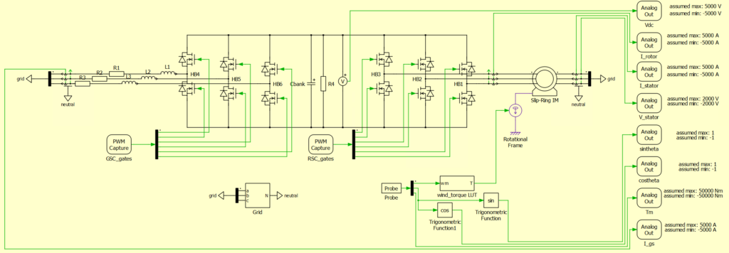
Following these approximations, a time-step of 6 µs was implemented to maximize the available resources on the HIL simulator. The plant subsequently implemented in PLECS is shown in Figure 8.
Implementing DFIG control on the B-Box RCP
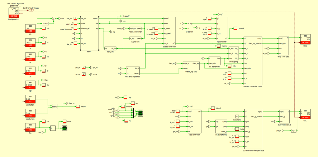
Implementing the control is trivial using the ACG SDK and Plexim PLECS. A screenshot of the control, which can be downloaded below, is shown in Figure 9.
The control frequency selected is 20 kHz, which still makes sense given the step size of 6 µs for the plant model.
Interfacing the B-Box RCP to the HIL simulator
In order to interface the B-Box RCP to the RT-Box 1, the HIL interface needs to be used. It can be connected as seen in Figure 10 below:
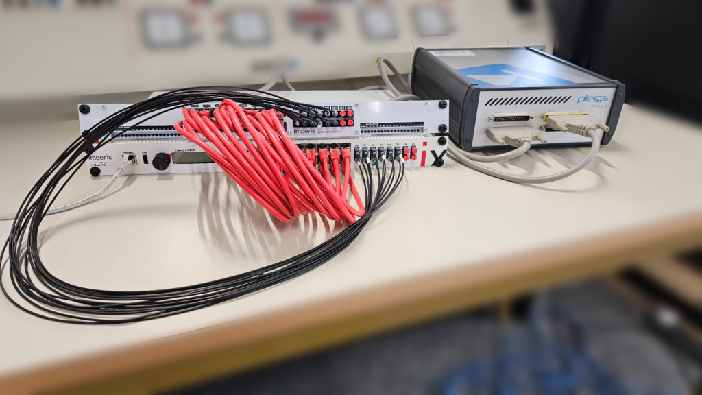
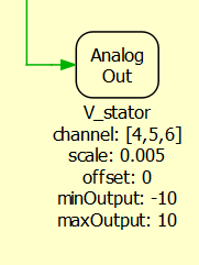
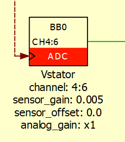
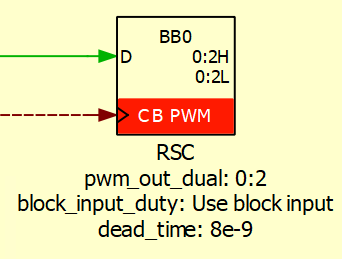
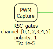
Since the HIL simulator and the B-Box RCP only accept analog signals between +10 V and -10 V, the signals must be scaled within these limits, as shown in Figures 11 and 12. Likewise, Figures 13 and 14 illustrate how to set the PWM capture block to accept the PWM outputs from the B-Box RCP.
Results
The following section demonstrates that the implemented DFIG control functions as intended.
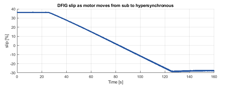
As expected, Figures 17 and 18 show how the RSC can operate the DFIG above (with a positive slip) and below (with a negative slip) synchronous speed. Additionally, Figure 17 demonstrates that the GSC converter maintains a high power factor while maintaining a fixed DC bus voltage, regardless of power flow direction.
As can be seen in Figures 17 and 18, when the DFIG is operating at synchronous speed (~157 rad/s), the rotor slip is equal to 0.
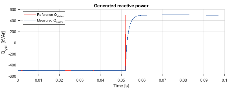
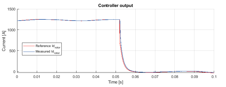
Further, figures 20 and 21 illustrate that the reactive power controller can both sink and generate reactive power according to the setpoint:
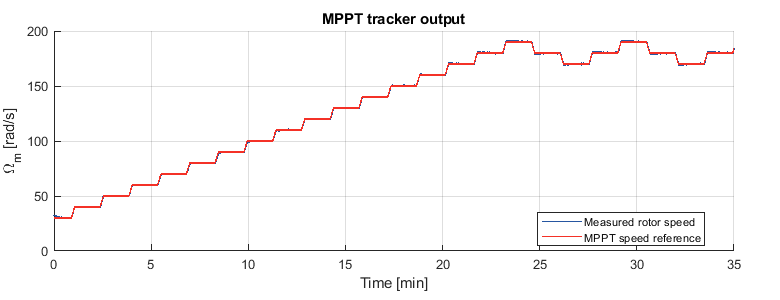
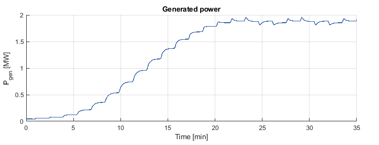
Finally, figures 23 and 24 prove that the MPPT tracking in the model is functioning as expected, tracking the generated power to the peak defined in Figure 15.
References
[1] G. Abad, J. López, M. Rodríguez, L. Marroyo, and G. Iwanski, Doubly Fed Induction Machine:
Modeling and Control for Wind Energy Generation, IEEE Press Series on Power Engineering,
Wiley, 2011.
[2] A. Petersson, “Analysis, Modeling and Control of Doubly-Fed Induction Generators for Wind Turbines”, PhD Thesis, Chalmers University of Technology, 2005.


