Table of Contents
Thanks to its flexible output voltage range, the LLC resonant converter is a popular choice of topology for battery charger applications, such as onboard chargers in EVs. Additionally, due to its soft switching capabilities, this converter can be operated at high switching frequencies, while maintaining excellent efficiency. This leads to compact magnetics and a high overall power density [1].
This technical note expands on the information provided in TN125 and provides an example of how an LLC resonant converter can be controlled in a realistic use-case scenario. Notably, as the battery rather constitutes a constant voltage than a constant resistance load, some of the developments presented in TN125 are adapted accordingly.
Resonant converter operation with constant output voltage
Unlike TN125, in which a resistive load is used, this article assumes that the output voltage is constant. This is a rough, but reasonable assumption for a large part of the voltage characteristics of most batteries. Moreover, and perhaps more importantly, for what regards the to-be-implemented power flow control, this assumption is also valid for any given point of the state of charge (SoC), because the battery voltage is relatively independent of the current that is pulled/pushed from/into it. In other words, the internal series resistance is low.
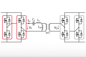
The considered system is shown in Figure 1. The inverter side is constituted by an active full bridge, whereas the rectifier side is not operated, i.e. only diodes are used.

To analyze the operation of the resonant converter in this particular scenario, some efforts are required. Indeed, most equations developed in TN125 are not directly applicable. Notably, the primary-referred equivalent resistance \(R_{ac}\) is not independent of the selected operating point \(V_{bat}\) and \(I_{charge}\), but rather a direct function of it:
$$ R_{ac} = \frac{8 n^2 V_{bat}}{\pi^2 I_{bat}} $$
Consequently, to analyze the converter operation leveraging usual techniques (notably under the first harmonic approximation, see TN125), each operating point must be evaluated individually, at the corresponding \(R_{ac} \). Then, the charging current characteristics can be established, as shown in Figure 2.
$$
\begin{align}
n &= 8/9 \\
L_r &= 21 \text{µH} \\
L_m &= 90 \text{µH} \\
C_r &= 110 \text{nF} \\
\end{align}
$$
$$
\begin{align}
L_n &= \frac{L_m}{L_r} = 4.3 \\
\omega_r &= \frac{1}{2 \pi \sqrt{L_r C_r}} = 105 \text{kHz}
\end{align}
$$
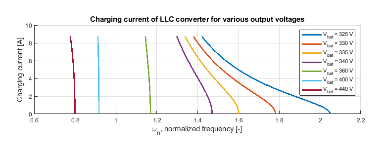
The observation of Figure 2 raises the following remarks:
- At low battery voltages – hence operating points with relatively low equivalent load resistances – large variations of the switching frequency are required to operate the resonant converter throughout its complete current range.
- Conversely, at high battery voltages – hence operating points with relatively high equivalent load resistances – even a small variation of frequency may induce a large change in the output current.
These differences in the sensitivity of the frequency toward the output current may pose a challenge to the design of the current control. Indeed, using terms of conventional control theory, the gain of the plant \(G = \frac{I_{bat}}{\omega_{n}} \) varies significantly with the output voltage (i.e. SoC). This may become a challenge for the design of a suitable control implementation.
It is worth noting here that these relatively large differences in the plant gain are a direct consequence of the selected tank design. Notably, a lower inductance ratio \(L_{n} \) would have resulted in a more compact set of curves (reduced frequency range), and reduced variations of the plant gain. However, a lower \(L_{n} \) would also have resulted in comparatively lower efficiency near the resonance frequency, implying a direct trade-off between controllability and efficiency.
Resonant converter power flow control
Current control implementation
Following the assumption that the battery voltage is constant (as a function of the load current, as well as of the state of charge), current control is sufficient to manipulate the transferred power.
Controller tuning
As discussed above, defining a plant model for the control of the output current based on the switching frequency is a complex task. Figure 2 has indeed revealed that the plant model should vary with the operating point. Besides, the same figure also reveals that the relationship \(I_{bat} = f(\omega) \) is non-linear.
Given that complexity, control design is an uneasy task, which may call for advanced control techniques [2], or conventional PI-based control with gain scheduling [3].
In this article, an empirical approach is used, tuning the controller gains for the steepest gradient in Figure 2, which corresponds to the highest battery voltage. Logically, it is expected that this would result in a performance reduction for the transient response at lower battery voltages.
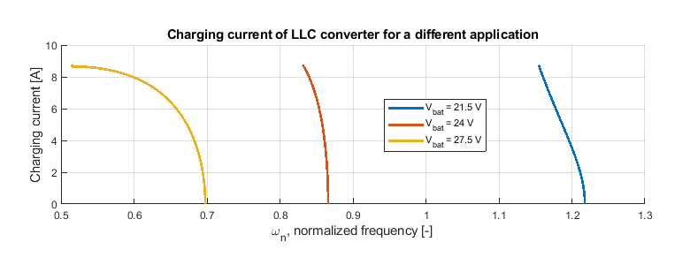
However, it is worth noting that, for another resonant converter design, the steepest gradient may not correspond to the same charging curve. For instance, Figure 3 shows the charge characteristics of a different design, in which the steepest curve applies to the lowest battery voltage. As such, establishing and carefully analyzing the charge characteristics should be recommended before any control design.
Saturation limits
Lower saturation limit
Proper saturation of the current controller output is required to enforce that the LLC resonant converter is operated in the region where \(I_{bat} = f(\omega) \) is monotonic, and where Zero Voltage Switching (ZVS) is guaranteed. For each operating point, this corresponds to frequencies above the resulting resonance and must be guaranteed by the lower saturation limit.
However, as this resonance shifts to higher frequencies with an increasing quality factor (hence output current), the lower limit must be adapted as a function of the current.
Upper saturation limit
Two main criteria shall be considered to determine the upper saturation limit:
First, technical limitations of the power stage or switching losses may define a maximum switching frequency.
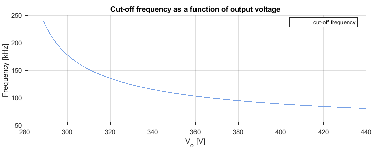
Second, the voltage gain offered by the resonant converter shall also be sufficient to guarantee the proper operation of the rectifier stage. Otherwise, the rectification diodes would be permanently reverse-biased, thereby preventing any current flow to the battery. Using time interval analysis, [4] showed that the frequency at which the output current reaches zero can be calculated with the following equation:
\(f_{co} = fr \frac{\sqrt{\frac{L_n^{-1}}{1 + L_n^{-1}}}\frac{\pi}{2}}{\cos^{-1}(\frac{1}{\frac{n V_o}{V_i}(1+L_n^{-1})})}\)
[4] refers to the operating frequency at which the rectification diodes are always reverse-biased as the “cutoff frequency”. Figure 4 plots this frequency as a function of the battery voltage.
Limiting overshoot
Finally, due to the non-linear nature of the resonant converter, its closed-loop control is particularly vulnerable to overshoot. Therefore, anti-windup is recommended, such that the impact of temporary saturation is minimized.
LLC resonant converter prototype
Experimental setup
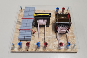
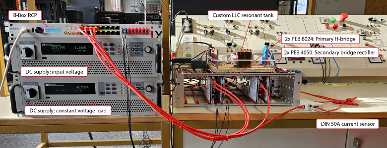
To illustrate the above-presented content and validate the corresponding operation experimentally, a prototype can be built using imperix products. Figure 5 shows a picture of the proposed setup.
The employed set of equipment is as follows:
- 1x B-Box RCP, used as programmable controller
- 2x PEB 8024, used to create a SiC H-bridge that is capable of switching at up to 200 kHz
- 2x PEB 4050, used without any gate signals (IGBTs have superior body diodes in comparison to the SiC-based modules)
- 1x custom resonant tank, as described in TN127
- 1x DC power supply, used as input voltage, with a constant voltage set to 340 V
- 1x reversible DC power supply, used as a battery emulator at the output, with a configurable voltage.
Alongside the setup described above, the recommendations outlined in TN181 were followed to maximize safety when working in the lab.
Simulink-based control algorithm
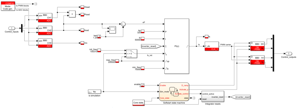
The corresponding control model is shown in Figure 5. It is available for download using the following link.
This control model uses a constant sampling and control frequency, set to 20kHz. On the other hand, the CLK block is used to manipulate the switching frequency. More information about this approach is given in PN121.
The upper saturation limit is set to the maximum suggested switching frequency by the PEB 8024 datasheet.
Furthermore, to avoid an excessive tank current at startup, a soft-start procedure is implemented, similar to that described in TN115.
Experimental results
Figures 6 and 7 show various step responses, corresponding to the operation of the resonant converter above and below resonance.
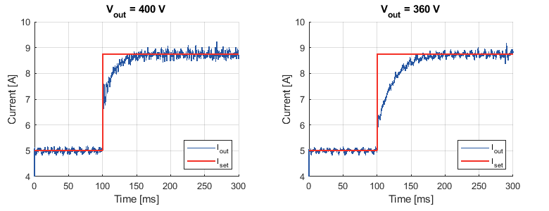
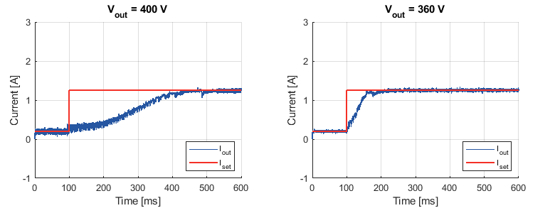
As expected considering Figure 2, the results shown in Figure 8 reveal that the transient response to a reference step is faster for high output voltages, which corresponds to a higher plant open-loop gain.
On the other hand, Figure 7 demonstrates that, for very small values of the output current, the transient response to a reference step is slower at a high output voltage. A possible lead toward the explanation of this counter-intuitive result lies in the underlying approximations (notably the First Harmonic Approximation – FHA), which are reaching their limits for such small current values.
References
[1] Wen-Jian Gu and Rui Lui, “A Study of Volume and Weight vs. Frequency for High-Frequency Transformers,” in Proc. of PESC Conference, Seattle, 1993.
[2] W. Feng, F. C. Lee, and P. Mattavelli, “Simplified Optimal Trajectory Control (SOTC) for LLC Resonant Converters,” in IEEE Transactions on Power Electronics, May 2013.
[3] S. W. Kang, H. J. Kim, and B. H. Cho, “Gain-scheduled control using voltage controlled oscillator with variable gain for an LLC resonant converter,” in Proc. of ECCE Conference, Pittsburgh, USA, 2014.
[4] J. F. Lazar and R. Martinelli, “Steady-state analysis of the LLC series resonant converter,” in Proc. of APEC, Anaheim, CA, USA, 2001


