Table of Contents
Unlike continuous PWM, where the pulse width is modulated throughout the entire switching cycle, Discontinuous PWM introduces breaks or gaps in the modulation process. These breaks can be intentional and are typically designed to reduce switching losses, improve efficiency, or meet certain harmonic distortion requirements. The term “Discontinuous PWM” is coined due to the utilization of modulating signals in these schemes, characterized by their discontinuous nature over time. This unique characteristic is achieved through a method known as zero-sequence voltage injection.
A readily applicable Simulink model is presented, encompassing the six most widely employed discontinuous PWM methods, as well as their experimental validation using standard imperix tools.
The experimental results presented in this article are based on a two-level three-phase inverter, whose topology is depicted below.
Introduction to Discontinuous PWM
Power conversion is commonly achieved through a switched-mode approach, where a trade-off between switching frequency and switching losses has to be considered. This trade-off is influenced by the characteristics of the chosen PWM method [1].
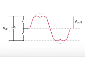
While producing a sinusoidal phase voltage with a two-level inverter, the peak amplitude is limited by the DC-bus voltage. Based on the illustration below, each leg of the inverter can produce a leg voltage \(v_{leg}\) of \(V_{DC}/2\), corresponding to a relative amplitude of the output voltage, often referred to as the modulation index, of \(m=1\). In the case of Sinusoidal Pulse Width Modulation (SPWM), the output voltage is clipped to \(±V_{DC}/2\) for \(m>1\), and the converter is said to be in the overmodulation region.
The discontinuous PWM is a carrier-based method relying on the fundamental principle of saturating the reference voltage signals \(V_{A}^{\star},V_{B}^{\star},V_{C}^{\star}\) for 120° within a 360° cycle, intentionally keeping one of the three converter legs without commutation, by injecting a zero-sequence common-mode voltage \(V_{0}\) to the phase voltages \(V_{A},V_{B},V_{C}\).
$$V_{A,B,C}^{\star}=V_{A,B,C}+V_0$$
The idea behind the Discontinuous PWM injection method is to add a rectangular zero sequence component at triple the fundamental frequency to the sinusoidal reference, which distorts the phase voltage references. This way, the peak voltage of the reference is reduced in comparison to a pure sinusoidal reference, and the modulation index can be increased up to \(m=2\sqrt3 ≈ 1.15\) before hitting the limit imposed by the DC-bus. This theoretical limit applies to all zero-sequence voltage injection PWM methods, including discontinuous PWM.
The main characteristics of DPWM are the following:
- Reduction in the number of commutations and, consequently, switching losses. For a defined value of allowable switching losses, the effective switching frequency can be increased by 3/2, resulting in a reduction of the RMS value of the mains current harmonics for high modulation index values. Consequently, a reduced filtering effort is required, as DPWM enables the use of smaller inductors and capacitors, contributing to an overall reduction in the size of passive components. This enhances power density and system integration in space-constrained applications.
- Equal loading of all the switches, as each switch conducts for 60°, reducing the requirement of thermal management of the semiconductors.
Enhanced DC-bus utilization in motor drive applications leads to a higher output voltage, broadening the motor’s speed range [2]. Moreover, achieving a higher DC-bus utilization is crucial for cost and power density improvements [3]. In grid-tie operations, a higher output voltage is advantageous for optimizing power output from renewable sources, ensuring seamless synchronization with the electrical grid, improving overall power quality, facilitating the integration of multiple energy sources, and efficiently feeding excess power back into the grid [4].
Zero-sequence signal generation for Discontinuous PWM
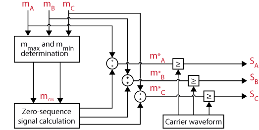
After normalizing the output reference voltage \(V_{peak_{DPWM}}\), three-phase sinusoidal modulation signals are generated. These modulation signals are named \(m_{A}\), \(m_{B}\), and \(m_{C}\). To clamp one of the phases to the positive or negative DC-bus, a common-mode signal is computed by evaluating the modulation signals. This computation is done using the formula provided in [5]:
$$m_{CM+}=1-\max\left(m_{A},m_{B},m_{C}\right)$$
$$m_{CM-}=-1-\min\left(m_{A},m_{B},m_{C}\right)$$
The injection of the common-mode signal into the initial modulation signals results in the following altered modulating signals:
$$m_{A}^{*}=m_{A}+m_{CM}$$ $$m_{B}^{*}=m_{B}+m_{CM}$$ $$m_{C}^{*}=m_{C}+m_{CM}$$
The resulting modulating signals are then compared with carrier waveforms to generate the gate signals \(S_{A}\), \(S_{B}\), and \(S_{C}\).
Classification of the Discontinuous PWM methods
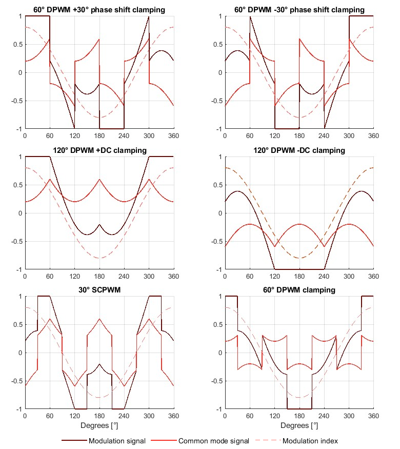
The authors in [6] propose a classification of the Discontinuous PWM methods based on the choice of the clamping strategy:
- Continual-clamp PWM (CCPWM) continually clamps each phase to one of the two DC-buses for 60° or 120° duration in each half of the fundamental cycle.
- One saturation of 120°: this corresponds to the methods “120° DPWM with -DC clamping ” or “120° DPWM with +DC clamping“.
- Two saturations of 60°: this corresponds to the methods “60° DPWM clamping“, “60° DPWM with +30° phase shift clamping”, and “60° DPWM with -30° phase shift clamping”. In general, the 60° clamping duration can be positioned anywhere during the voltage cycle. For an arbitrary γ (i.e., 0° ≤ γ ≤ 60°) this results in the expression [5]:
$$\begin{aligned}\left\lbrace\begin{matrix}m_{CM+},\left(30°+\gamma\right)<wt<\left(90°+\gamma\right)\\ m_{CM-},\left(90°+\gamma\right)<wt<\left(150°+\gamma\right)\end{matrix}\right.\end{aligned}$$
- Split-clamp PWM (SCPWM) divides the 60° clamping interval into two sub-intervals, which are not necessarily equal, and fall in two different quarter cycles.
- Four saturation of 30°: this corresponds to the strategy called “30° SCPWM“.
The generic zero-sequence signal for SCPWM can be obtained by swapping \(m_{CM+}\) and \(m_{CM-}\).
Whether continual clamp or split clamp, the positioning of the clamping interval, which depends on the power factor, plays a crucial role in minimizing switching losses, as further detailed in [5]. Discontinuous PWM has proved to showcase superior performances for high modulation indices [7-8], so a high-performance adaptive modulation algorithm could be implemented to swap between different modulation strategies according to the converter operating point [3].
Software resources
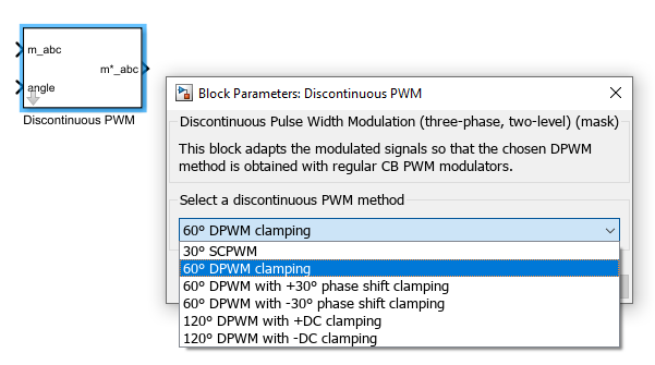
The following zip file contains a pre-implemented and pre-tested implementation of the six most common discontinuous Pulse Width Modulation methods for two-level three-phase inverters in the MATLAB Simulink environment using the ACG SDK. The usage of discontinuous PWM block is simple, as the user only needs to select the desired method.
The model can simulate the system’s behavior in an offline simulation and generate code for real-time execution on a B-Box RCP digital controller. The minimum requirements are:
- Imperix ACG SDK (latest version recommended)
- For control code development and simulation in Simulink:
- MATLAB Simulink R2016a or newer.
- Simscape Power Systems
Simulink implementation
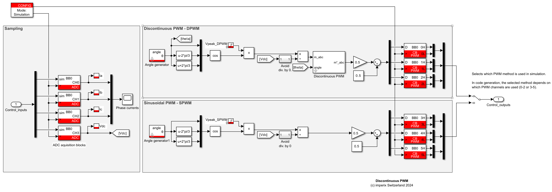
For comparison purposes, both Discontinuous PWM and SPWM methods are implemented in parallel, and the user can select which switching signals will drive the converter.
Experimental setup and results
During the experiments, a two-level inverter is connected to a balanced three-phase RL load, under the following conditions:
- DC-bus voltage: 100 V
- Control frequency: 20 kHz
- Sampling phase: 0.5 (middle of the switching period)
- Load resistance: 8.5 Ω
- Load inductance: 2.5 mH
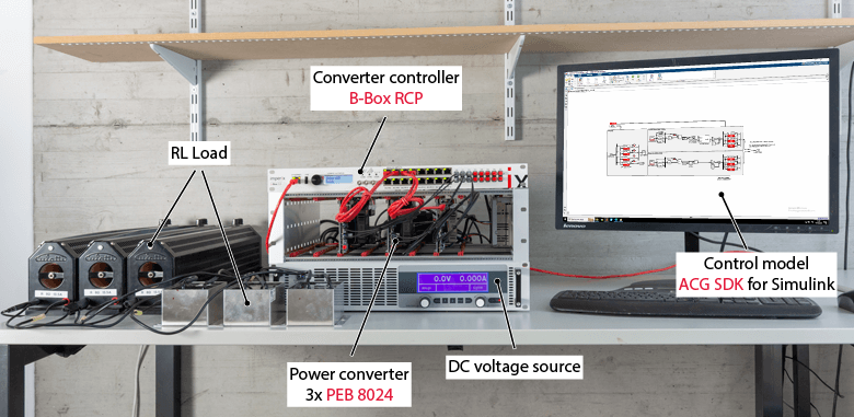
The experimental setup is presented in the picture below. The power converter is built from 3x PEB 8024 phase-leg modules.
Validation of the Discontinuous PWM methods
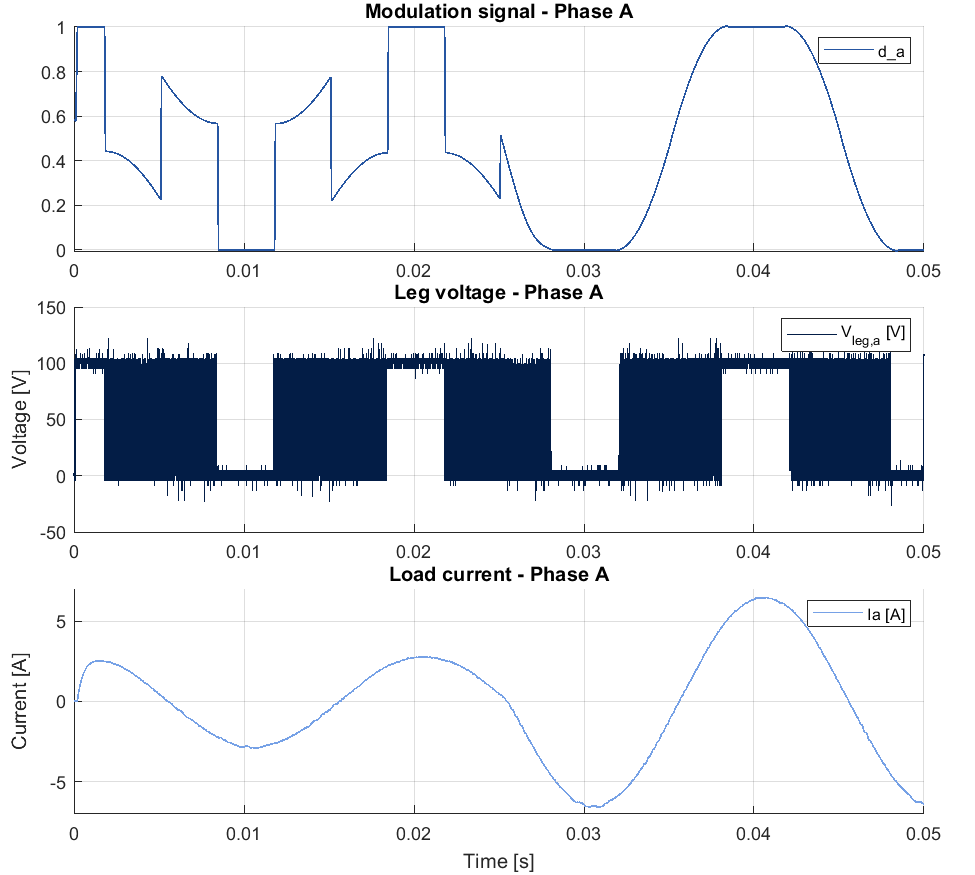
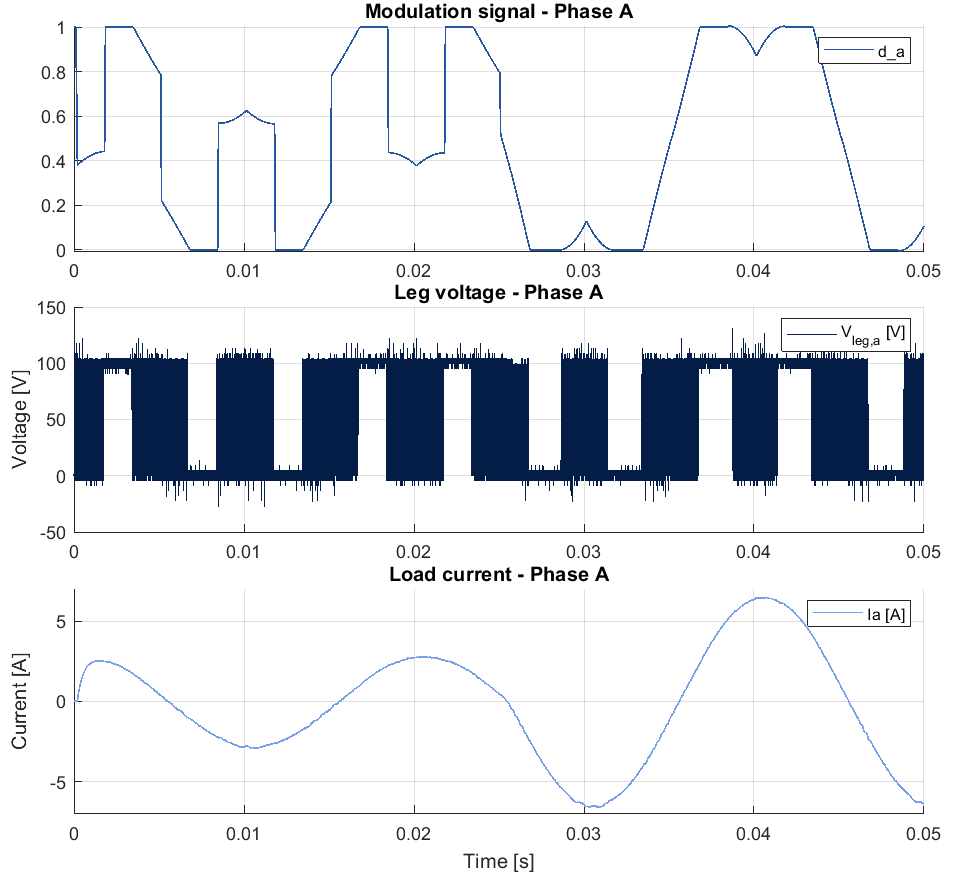
The experimental results for 60° Discontinuous PWM and 30° Split Clamp PWM are presented in this section. To verify the correct implementation of the provided Discontinuous PWM methods, the output reference voltage peak \(V_{peak_{DPWM}}\) is raised from \(50V\) to \(115V\) at \(t=0.25 s\).
The shape of the modulation signal varies depending on the reference output voltage and the chosen clamping method. Thus, when the reference output voltage increases to \(V_{peak_{DPWM}}=115V\) at \(t=0.25 s\), the modulation signals approach the overmodulation region with different shapes, leading to different overmodulation region characteristics [3].
The leg voltage \(V_{leg,a}\) shows the different phase clamping strategies of 60° DPWM and 30° SCPWM. The former clamps phase A with two saturations of 60°, whereas the latter clamps phase A with four saturations of 30°, as explained in Section 3. The two different clamping strategies however lead to the same load current, confirming the proper operation of the methods.
References
[1] J. Holtz, “Pulsewidth modulation for electronic power conversion,” in Proceedings of the IEEE, Aug. 1994.
[2] Q. An, J. Liu, Z. Peng, L. Sun and L. Sun, “Dual-Space Vector Control of Open-End Winding Permanent Magnet Synchronous Motor Drive Fed by Dual Inverter,” in IEEE Trans. on Power Electronics, Dec. 2016.
[3] A. M. Hava, R. J. Kerkman, and T. A. Lipo, “Carrier-based PWM-VSI overmodulation strategies: analysis, comparison, and design,” in IEEE Trans. on Power Electronics, July 1998.
[4] Q. -C. Zhong and T. Hornik, “Cascaded Current–Voltage Control to Improve the Power Quality for a Grid-Connected Inverter With a Local Load,” in IEEE Trans. on Industrial Electronics, April 2013.
[5] Das, S., Hari, V.S.S.P.K., Kumar, A., et al. “Analysis of generalized continual-clamp and split-clamp PWM schemes for induction motor drive”, Sadhana, 2019.
[6] F. Zaamouche, S. Salah, and L. Hamiche, “A Discontinuous PWM Techniques Evaluation by Analysis of Voltage and Current Waveforms”, International Journal of Scientific Research & Engineering Technology, 2018.
[7] A. M. Hava, R. J. Kerkman and T. A. Lipo, “A high-performance generalized discontinuous PWM algorithm,” in IEEE Trans. on Industry Applications, Sept.-Oct. 1998.
[8] O. Ojo, “The generalized discontinuous PWM scheme for three-phase voltage source inverters,” in IEEE Trans. on Industrial Electronics, Dec. 2004.


