Table of Contents
Introduction
This technical note presents the implementation of an interleaved buck converter (multiphase step-down converter) and details an appropriate sampling method of the different currents involved in the circuit. The implementation of an interleaved boost converter is explained here.
At first, the general principle of the converter and its benefits compared to a conventional buck will be presented. Then, technical insights on carrier interleaving and proper sampling are given. At last, a practical control implementation targeting the B-Box RCP or B-Board PRO with automated code generation as well as experimental results are provided.
Software resources
Interleaved buck converter principle
Single-leg step-down converters are well suited for low voltage, low current applications. However, with higher power ratings, multi-leg configurations become attractive. By interleaving the operation of converter legs, filtering requirements can often be facilitated, hence improving the overall power density and system dynamics.
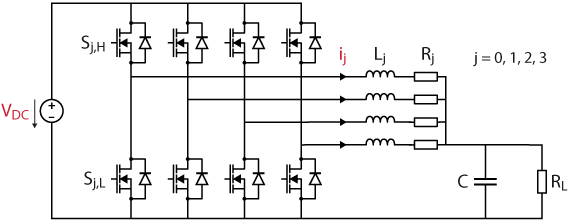
The architecture of a multiphase buck is presented below. It consists, in this case, of a four legs design.
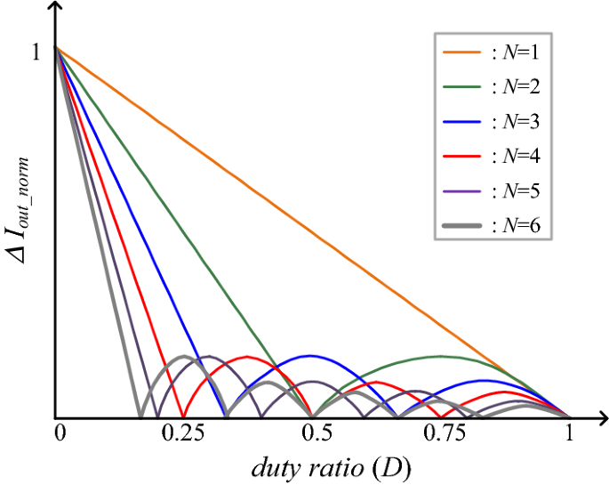
The primary benefit of a multiphase design is the possible reduction of the output current ripple, thanks to interleaving [1]. Indeed, by appropriately phase-shifting the current ripples of the individual buck converters, some ripple compensation can be achieved, as well as an increase of the apparent switching frequency.
Typically, a phase offset of \(\frac{2\pi}{N}\) is used in between legs, where N is the number of legs. The following graph, taken from [2], illustrates the magnitude of the output current ripple as a function of the duty cycle. It shows the possible reduction of the output current ripple depending on the number of legs. Also, this demonstrates that a perfect compensation of the current ripples can (theoretically) be achieved for specific duty cycle values.
Current sampling within an interleaved converter
In order not to reduce the achievable control bandwidth unnecessarily, synchronous sampling is often used for the control of buck converters. Typically, when sampling the current in the middle of the switching period, the retrieved, unfiltered, value is already equal to the average current value (provided that the converter operates in continuous conduction mode). Then, as explained in PN142: Discrete control delay identification, the latency of the control system can be easily identified and minimized, hence maximizing the achievable closed-loop bandwidth.
However, in an interleaved converter, achieving the same behavior isn’t trivial. Therefore, careful configuration of the sampling and implementation of the control is essential.
Case study: four legs interleaved buck converter
The objective of the following sections is to provide the key concepts to consider for the proper sampling configuration of interleaved converters. It is to be noted that, although these concepts would remain similar, the exact sampling configuration will differ depending on the number of interleaved converters. To provide a practical example, this article will consider the case of four interleaved buck converters.
Single sampling instant
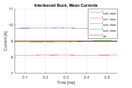
As aforementioned, interleaving buck converters is done by phase-shifting the current ripples. Sampling the different currents are the same time will then results in different instantaneous values, as illustrated below. This is therefore an inconvenient approach regarding the balancing of the current among the phase-legs.
Inconsistent control delays
Alternatively, sampling all currents in the middle of their respective ripple requires different sampling instants. Therefore, implementing phase-shifted sampling together with a unique computation loop unavoidably introduces different delays and results in inconsistent control dynamics, which are difficult to evaluate and tune. More details related to PI-based current control strategies can be found on PI controller implementation for current control.
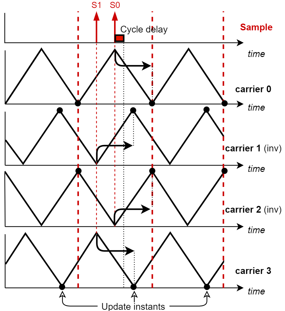
This drawback is illustrated in the figure below: without special care, samples of different “ages” are processed together, and the resulting PWM update time varies from one carrier to the other. Consequently, the overall control delay varies among the phase-legs.
A possible approach to mitigate this phenomenon would be to make sure that the duration of the computation itself is sufficiently long so that the PWM parameters resulting from the most recent samples are not updated “too early”. For instance, if the duration of the computation ranges from 50% to 75% of the PWM period, all phase-legs feature the same overall control delay.
A solution for four interleaved legs
With four phase-legs, a preferable sampling configuration would be to:
- Configure only two sampling instants, one with a phase offset of 90° and another with an offset of 180°
- Configure the PWM update instant at the top of the triangles for carrier 1 and carrier 2.
Doing so, every current will be sampled in the middle of its ripple which will ensure proper balancing of the total current among the phase-legs.
The total control delay is also guaranteed to be the same for each individual buck converters, as long as the computation time is shorter than 25% of the PWM period. The same parameters can therefore be used for the controller of each converter leg.
For more information about oversampling and the configuration of multiple sample phases, please refer to PN154. Note also that it is not possible to configure the sampling of imperix controller exactly as depicted in the above figure. Indeed, as explained in the aforementioned article, it is only possible to configure evenly distributed sampling events over the control period. To achieve the above scenario, the control model provided below is then configured with four sampling instants and only uses the first two.
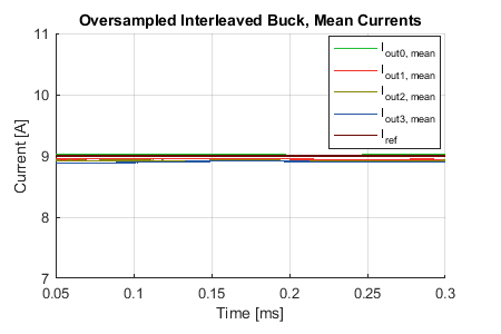
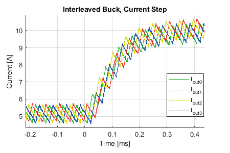
The following graph show the resulting current control with this recommended scenario. It is clear that the currents are shared equally.
B-Box / B-Board implementation
To exemplify the suggested implementation, the following figure shows a parallel between the carriers and the Simulink blocks. It illustrates the two sampling instants as well as the ADC and PWM block configuration
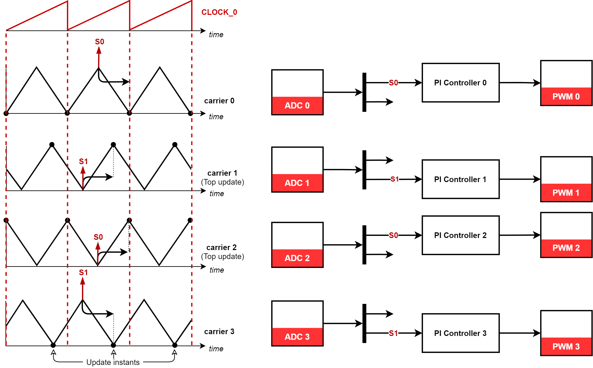
The imperix Simulink blocks configurations required are detailed in the tables below.
| Block | CONFIG |
| Sampling phase | 0.5 |
| Number of sampling events | 4 |
| Block | ADC 0 | ADC 1 | ADC 2 | ADC 3 |
| History depth | 4 | 4 | 4 | 4 |
| Selected output sample | 0 | 1 | 0 | 1 |
| Block | PWM 0 | PWM 1 | PWM 2 | PWM 3 |
| Carrier type | triangle | inv. triangle | inv. triangle | triangle |
| Carrier phase | 0 | 0.75 | 0 | 0.75 |
Note that this control algorithm has been implemented in Simulink but it would be done very similarly in PLECS. The picture below illustrates all the different blocks involved in the control.

Experimental setup and results
Required hardware
- 1x B-Box RCP, programmable controller
- 4x PEB 8038, half-bridge power modules
- 1x passive filter box
- A DC power supply (At least 100V 5A)
- 4x Resistors (5Ω to 100Ω)
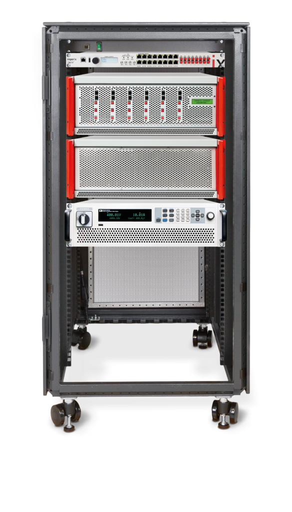
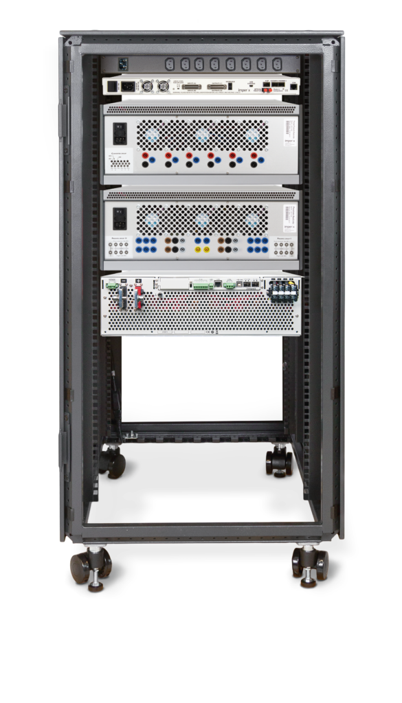
The power electronics test bench contains all the required imperix equipment for this experimental setup.
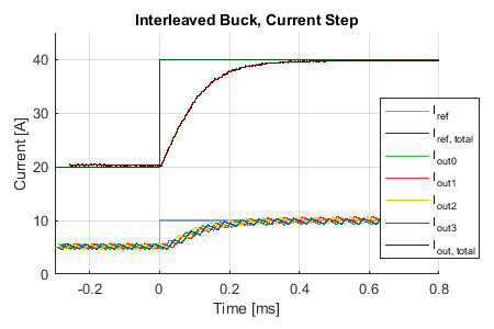
In the end, this solution demonstrates satisfying experimental results. The interleaved buck converter performs well under a current step of 20 to 40 [A]. The effectiveness of the converter in reducing the output current ripples is undeniable. The four currents are interleaved as expected and remain properly balanced under a reference step.
Academic references
[1] High Efficiency, High Density, PolyPhase Converters for High Current Applications
[2] Current-balancing strategy for multileg interleaved DC/DC converters of electric-vehicle chargers


