Table of Contents
This article explains why the lack of inertia in grid-forming inverters can impact the grid and how to alleviate the issue with a virtual synchronous generator.
A demonstration code example is provided and freely available. It can be tested in simulation using imperix ACG SDK and validated in the laboratory with a TPI8032 22kW programmable inverter.
Stabilization of the grid frequency with inertia provision
In a conventional grid, synchronous generators stabilize the frequency thanks to their rotational inertia and droop control algorithms. With the advent of distributed energy resources, a significant share of the power generation is expected to come from grid-forming inverters (TN168), which do not have any rotational inertia. This lack of inertia can adversely affect the frequency regulation capability of the grid and lead to unstable conditions, and more generally malfunctioning of the connected devices [1].
One possible solution is to emulate the properties of synchronous generators with inverters and provide virtual inertia through a synchronous machine emulation control technique, like the virtual synchronous generator control [2]. These so-called virtual synchronous generators are essentially grid-forming inverters that replicate the swing equation of a generator in addition to the droop curves.
It can be observed that, for an increase in load, a synchronous generator slows down the speed at which it is rotating, with a dynamic that depends on the inertial mass of the generator. With the same concept, the virtual synchronous generator changes the reference frequency according to the virtual inertia and the amplitude of the load step. The maximum Rate of Change of Frequency (RoCoF), specified in applicable standard prescriptions, sets a lower bound for the required value of the virtual inertia [3].
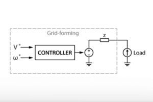
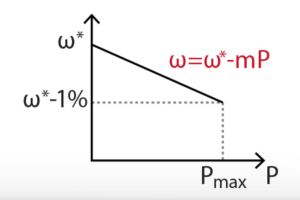
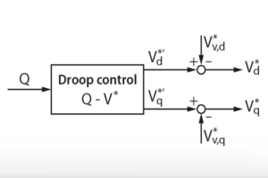
The overall control scheme of a grid-forming inverter with a virtual synchronous generator feature is shown below. It is similar to a proportional droop control (TN169) but the active power controller is modified to include the swing equation of a synchronous generator.
Implementation of a virtual synchronous generator
The virtual synchronous generator control is based on a physical equation called the swing equation. The swing equation mimics the inertia of a generator and thus can be added to the traditional droop control to enhance its transient state performance. The proportional droop control implementing a swing equation can be expressed as [4]:
$$P-\frac{d\omega}{m}=J\omega_0\frac{\mathrm{d\omega}}{\mathrm{dt}}$$
where \(m\) is the frequency static droop coefficient, \(J\) the virtual inertia, \(\omega_{0}\) the nominal frequency, \(\omega^{\star}\) is the reference frequency, \(d\omega=\omega^{\star}-\omega_{0}\) is the frequency variation. Starting from this equation, it can be easily demonstrated that the droop control is a particular case of virtual synchronous generator control, where the inertia value equals zero [4].
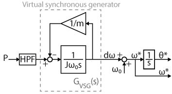
The block diagram of a droop controller including the swing equation is shown in the following figure, where \(\theta^{\star}\) is the reference phase angle.
The transfer function for the virtual synchronous generator controller \(G_{VSG}\left(s\right)\), whose pole placement depends on the value of the virtual inertia \(J\), can be expressed as [3]:
$$G_{VSG}\left(s\right)=\frac{m}{s\tau_{J}+1_{}}$$
where \(\tau_{J}=mJ\omega_{0}\) is the inertial time constant. As seen for the proportional droop control (TN169), the choice of the static droop coefficient \(m\) represents the slope of the droop curve and therefore has no effect during transients. On the other hand, the inertial time constant \(\tau_{J}\) allows for acting on the resulting RoCoF. Therefore, to ensure that the maximum RoCoF requirement is observed for a maximum active power step as follows, \(\tau_{J}\) can be designed as follows [3]:
$$\tau_{J}=\frac{m}{{}\rho}P_{max}$$
where \(\rho\) is the maximum allowable RoCoF and \(P_{max}\) is the maximum active power step.
Practical implementation of a virtual synchronous generator
Software resources for virtual synchronous generator
The control models available here after are implemented in Simulink using the imperix ACG SDK blockset. The models can both simulate the behavior of the system in an offline simulation and generate code for real-time execution on the controller of TPI 8032. An introductory guide regarding the TPI is addressed in getting started with the TPI 8032 (PN190). To run these models, the minimum requirements are:
- Imperix ACG SDK 2024.2 or newer.
- MATLAB Simulink R2016a or newer.
- For simulation only: Simscape Electrical
- TN170_GFMI_Virtual_synchronous_generator includes the virtual synchronous generator control for a grid-forming inverter connected to a passive load through an inductive line. This implementation requires one TPI 8032.
- TN170_GFMI_and_GFLI_Virtual_synchronous_generator includes the virtual synchronous generator control and a grid-following inverter acting as an active load connected through an inductive line. This implementation requires two TPI 8032.
The active power control featuring the virtual synchronous generator is implemented in Simulink as follows:

The high-pass filter (HPF) is introduced to restore the nominal grid frequency in steady-state. Further information about the HPF is addressed in TN169.
Experimental setup
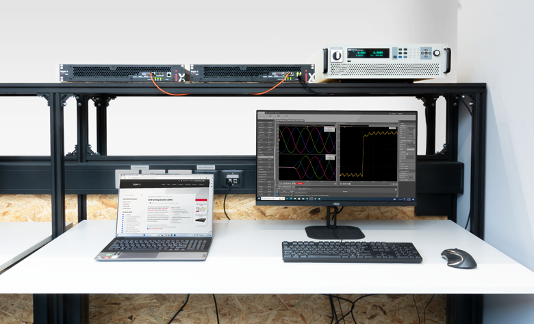
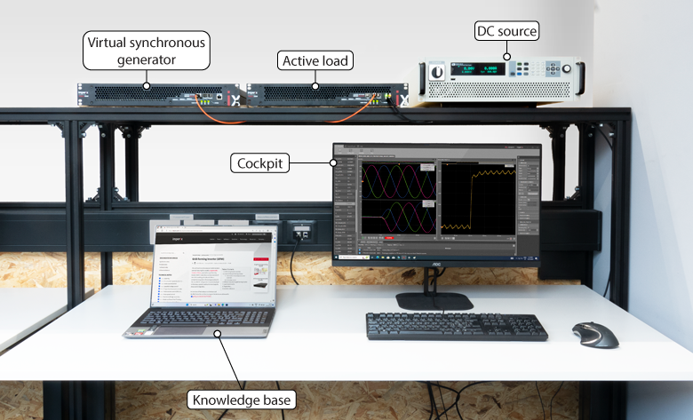
The experimental validation of the virtual synchronous generator is carried out with two TPIs used in a master-slave configuration, meaning that they are programmed from the same Simulink model. The virtual synchronous generator control is implemented on the master unit, connected through an SFP cable to the slave GFLI unit acting as an active load. Therefore the required equipment is:
- 2x TPI 8032 three-phase inverter
- ACG SDK toolbox for automated generation of the controller code from Simulink or PLECS
- 1x bidirectional DC power supply (800V)
- 3x 2.2mH inductors
- All the necessary cables
The maximum allowed RoCoF is typically imposed by the transmission system operator (TSO) and therefore can change depending on the location. The maximum RoCoF \(\rho\) is set arbitrarily as 1 Hz/s in this experiment for the maximum active power \(P_{max}\) of 18 kW. For a given maximum RoCoF \(\rho\), the value of the corresponding minimum virtual inertia \(J\) that complies with the imposed limit can be derived as [4]:
$$J=\frac{\tau_{J}}{m\cdot\omega_0}=\frac{\frac{m}{{}\rho}P_{max}}{m\cdot\omega_0}=\frac{0.5\left\lbrack s\right\rbrack}{m\cdot\omega_0}=9.12\, \operatorname{kg\cdot m^2}$$
| Parameter | Symbol | Value |
| Nominal grid frequency | \(\omega_{0}\) | 314 rad/s |
| Nominal grid voltage (RMS) | \(V_{0}\) | 230 V |
| Maximum frequency deviation | \(d\omega\) | 3.14 rad/s |
| Maximum voltage deviation | \(\Delta V\) | 23 V |
| Maximum RoCoF | \(\rho\) | 6.28 rad/s^2 |
| Rated power of the VSG | \(P_{max}\) | 18 kW |
Two tests are carried out to verify the effectiveness of the virtual synchronous generator control. The first test employs the inertia value derived from the latest equation, whereas in the second test half of the initial inertia is used to compare the resulting difference.
$$\, \text{1)}\,J=9.12\, \operatorname{kg\cdot m^2}$$
$$\, \text{2)}\,J/2=4.56\, \operatorname{kg\cdot m^2}$$
For each test, a step of active power from 0 to 18 kW is performed at t=1ms. The resulting frequency variation is shown in the following figure.
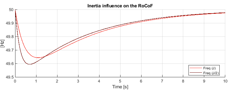
The resulting RoCoF and minimum frequency value, evaluated from t=1ms to t=200ms, are:
| Test n.1 | \(J\) |
| RoCoF [Hz/s] | Min [Hz] |
| 0.80 | 49.64 |
| Test n.2 | \(J/2\) |
| RoCoF [Hz/s] | Min [Hz] |
| 1.35 | 49.59 |
The inertia value selected in the first test meets the maximum RoCoF requirement of 1 Hz/s. Conversely, the maximum RoCoF is exceeded in the second test, where half of the initial inertia value is adopted. These results show how the virtual inertia directly influences the RoCoF and thus how the inertia can be tuned accordingly to meet the specific RoCoF requirement. The minimum frequency values during the transient are within the imposed limitations in both tests.
Academic References
[1] H. -P. Beck and R. Hesse, “Virtual synchronous machine,” in 9th International Conference on Electrical Power Quality and Utilisation, Barcelona, 2007, doi: 0.1109/EPQU.2007.4424220.
[2] J. Driesen and K. Visscher, “Virtual synchronous generators,” in IEEE Power and Energy Society General Meeting – Conversion and Delivery of Electrical Energy in the 21st Century, Pittsburgh, 2008, doi: 10.1109/PES.2008.4596800.
[3] D. B. Rathnayake, R. Razzaghi, and B. Bahrani, “Generalized virtual synchronous generator
control design for renewable power systems” in IEEE Trans. on Sustainable Energy, 2022, doi: 10.1109/TSTE.2022.3143664.
[4] J. Liu, Y. Miura, and T. Ise, “Dynamic characteristics and stability comparisons between virtual
synchronous generator and droop control in inverter-based distributed generators,” in IPEC, Hiroshima, 2014, doi: 10.1109/IPEC.2014.6869789.


