Table of Contents
This technical note explains how to implement speed control for an electric motor. First, the note introduces the general operating principles of motor speed control, regardless of which type of motor is used. Then, the speed controller is tuned using the symmetrical optimum method. Finally, a practical control implementation on a laboratory-scale electric drive (motor and inverter) is introduced, targeting the B-Box RCP or B-Board PRO with the ACG SDK on Simulink. Please note that imperix offers a ready-to-use motor drive system to develop and test motor control techniques. More details can be found in the Motor Testbench quick start guide.
General principles of motor speed control
An electric motor can be modeled mechanically as a rotating mass. Its inertia \(J_m\) can be rotated by applying a torque on it, which is the difference between electromagnetic torque \(T_{em}\) and a load torque \(T_L\). The load is external to the motor and cannot be controlled. However, the speed ωm of the motor can be changed by controlling the electromagnetic torque.
The relation between the speed, the inertia, and the torque is formalized by the second law of Newton for rotational movement [1]:
$$(1) \qquad k_F \omega _m + J_{m} \frac{d \omega _m}{dt} = T_{em} – T_L $$
\(T_L\) is the external load torque applied to the shaft and \(k_F \omega_m\) is the torque due to the friction. The transfer function linking the torque to the speed is then:
$$(2) \qquad H_1 (s) = \frac{\omega _m(s)}{T_{em}(s) – T_L} = \frac{1/k_F}{1 + s \space J_m/k_F} = \frac{K_{1}}{1 + s \space T_{1}} $$
In most applications, the effect of friction is negligible in comparison to the load and motor torque. In this case, the transfer function simplifies to:
$$ (3) \qquad H_2 (s) = \frac{\omega _m(s)}{T_{em}(s) – T_L} = \frac{1}{s \space J_m} = \frac{1}{s \space T_{2}} $$
Tuning of the digital speed control
According to the transfer function derived above, the plant is a 1st order system. Therefore, a PI controller is sufficient to follow a constant reference with no permanent error. Since the simplified plant from (3) contains a pure integrator, the proportional and integral terms are tuned using the symmetrical optimum criterion [1][2].
$$(4) \qquad \left\{ \begin{array} \displaystyle T_n &= 4 \space T_{tot}\\[5pt] \displaystyle T_i &= 8 \space T_{tot}^2 / T_2\\[5pt] \displaystyle K_p &= T_n \space / \space T_i \\[5pt] \displaystyle K_i &= 1 \space / \space T_i \end{array} \right. $$
The parameter Ttot represents the total delay of the discrete control, which can be computed using the PN142. An numerical example is presented below.
The symmetrical optimum criterion is sensitive to abrupt changes on the reference value. In this case, a setpoint corrector can be used in order to reduce the overshoot [2]:
$$(5) \qquad H_{setpoint,corrector}(s) = \frac{1}{1 + s \space T_2} $$
An alternative is to use a rate limiter to limit the variation rate of the motor speed reference.
Cascaded motor torque and speed control
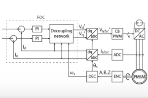
The motor speed controller generates only a torque reference and, therefore, must be cascaded with a torque controller in order to produce an effect on the motor. The torque controller can be implemented using, for instance, Field-Oriented Control or Direct Torque Control (AN004).
As developed above, the tuning of the speed controller depends on the total control delay, which can be computed as in PN142. In the case of the motor speed control, the speed controller is the outer control loop and the torque controller is the inner loop.
The overall cascaded control diagram is shown below.
Speed control implementation with ACG SDK on Simulink
The ACG SDK is a toolbox for Simulink and PLECS that enables quick and easy graphical programming of a B-Box or B-Board power electronics controller. This section describes the motor speed control implementation and its experimental validation with imperix prototyping tools. The Simulink and PLECS models can be downloaded below:
Cascaded motor speed control
The figure below shows the implementation of a cascaded control structure with a Field-Oriented Control as the torque controller. A Finite State Machine (FSM) oversees the operation of the motor. In particular, the FSM receives the desired speed (in rpm) from the user and limits its variation rate to reduce the overshoot of the speed controller.
Motor speed controller structure
In this application example, the speed controller is executed 100 times slower than the torque control. This way, the torque controller has enough time at its disposal to regulate the stator currents before the reference from the speed control is updated. Notice that with FOC, the torque reference must be translated into a current reference, using the equation developed in TN111.
Tuning of the motor speed controller
Here is a complete numerical example of how to tune the PI of the digital speed control loop. The motor parameters are presented in the Experimental results section.
The tuning of the inner loop of the cascaded control is detailed in TN111. As a reminder:
$$(6) \qquad \left\{ \begin{array} \displaystyle T_{tot,inner-loop} &= 75 \,\text{µs}\\ \displaystyle K_{p,inner-loop} &= 80.95 \,\Omega\\ \displaystyle K_{i,inner-loop} &= 22675.7 \,\Omega\,\text{s}^{-1} \end{array} \right. $$
The first step is to identify the transfer function of the speed controller:
$$(7) \qquad H_2 (s) = \frac{1}{s \space J_m} = \frac{1}{s \space T_{2}} = \frac{1}{s \space 2.9 \times 10^{-4} \,\text{kg} \,\text{m}^2} $$
The determination of the delays along the control chain of a cascaded control is explained in PN142. In this Simulink implementation, the outer-loop was chosen to the N=100 times slower than the inner-loop. Consequently, the various delays are:
$$(8) \qquad \left\{ \begin{array} \displaystyle T_{sens} \approx 0 \\[5pt] \displaystyle T_{ctrl} = N \times T_s = \cfrac{100}{20 \, \text{kHz}} = 5 \,\text{ms}\\[5pt] \displaystyle T_{PWM} = \cfrac{T_{sw}}{2} = \cfrac{1}{2 \times 20 \, \text{kHz}} = 25 \,\text{µs} \end{array}\right.$$
The total delay of the outer-loop is then the sum of the small time constants:
$$(9) \qquad T_{tot} = T_{sens} + T_{ctrl} + T_{PWM} = 5.025 \,\text{ms} $$
According the symmetrical optimum criterion, the parameters of the PIs are computed as:
$$(10) \qquad \left\{ \begin{array} \displaystyle T_n &= 4 \space T_{tot} = 20.1 \,\text{ms}\\[5pt] \displaystyle T_i &= 8 \space \frac{T_{tot}^2}{T_2} = 0.697 \,(\text{N}\,\text{m})^{-1} \\[5pt] \displaystyle K_p &= T_n \space / \space T_i = 0.029 \, \text{N}\,\text{m}\,\text{s}\\[5pt] \displaystyle K_i &= 1 \space / \space T_i = 1.43 \,\text{N}\,\text{m} \end{array} \right. $$
Experimental results
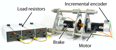
The experimental setup consists of a PMSM supplied by voltage source inverter controlled by a B-Box prototyping controller. The FOC control is implemented using the graphical programming of ACG SDK library for Simulink. The power converter is built from 4x PEB 8032 phase-leg modules (3 phases and 1 braking chopper leg). Another PMSM connected to 3 power resistors is used a brake to generate a load torque.
Motor parameters
The motor speed controller was validated on a Unimotor fm Permanent Magnets Synchronous Motor (PMSM) from Control Techniques.
| Parameter | Value | Unit |
| Rated power | 1.23 | kW |
| Pole pairs | 3 | – |
| Rated phase voltage | 460 | V |
| Rated phase current | 2.7 | A |
| Rated mechanical speed | 314 | rad/s |
| Rated torque | 3.9 | Nm |
| Stator resistance | 3.4 | Ohm |
| Stator inductance (d and q axis) | 12.15 | mH |
| Permanent magnet flux that encircles the stator winding | 0.25 | Wb |
| Moment of inertia (PMSM only) | 2.9 | kg cm2 |
Test conditions
- Load torque: 2 Nm (PMSM with resistors as load)
- DC link voltage: 500 V
- Inverter: 4x PEB8032 (one leg for braking chopper)
- Interrupt and sampling frequency: 20 kHz
- Sampling phase: 0.5
- PWM outputs: carrier-based
- Torque control technique: Field-Oriented Control (FOC)
Results
The tracking performance of the motor speed controller was validated experimentally by applying a speed reference step from 0 to 1500 rpm. The experiment was performed twice, with two different rate limits on the speed reference.
At first, the rate limiter was set to 100000 rpm/s. As shown below, the PMSM is unable to accelerate at this rate because the speed controller hits its upper saturation limit (1.1 pu of the nominal torque). Additionally, the tuning from the symmetrical optimum criterion leads to an overshoot of 21%.
For the second run, the reference variation was limited to 5000 rpm/s. In this case, the speed control is able to follow the acceleration of the speed reference. Since the control uses a 1st order PI controller, it is not able to completely eliminate the tracking error during the ramp. However, this has the advantage that the mechanical stress on the motor is also reduced since the control does not abruptly apply a high torque at startup. What’s more, the overshoot is also reduced to only 4.7%. The only drawback compared to the first experiment is the prolonged settling time of 0.4 s, compared to 0.3 s.


The choice of the speed reference rate limitation is a trade-off between the settling time and the mechanical stress induced by a sudden change of the torque.
Academic references
[1] Slobodan N. Vukosavić ,”Digital Control of Electrical Drives”, Springer, 2007, ISBN 978-0-387-25985-7
[2] Hansruedi Bühler, “Réglage de systèmes d’électronique de puissance – Volume 1: théorie”, Presses Polytechniques et Universitaires Romandes, 1997, ISBN-10: 2-88074-341-9


