Table of Contents
This page covers a possible control algorithm for controlling the secondary DC voltage of a DAB converter. A working prototype is built using PEH full-bridge power modules and is controlled with a B-Box digital controller.
What is a DAB converter?
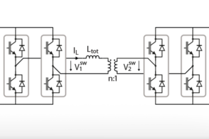
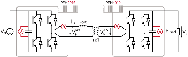
The DAB converter (Dual Active Bridge) is a bidirectional isolated DC/DC converter. It consists of two full bridges isolated by a high-frequency transformer. The full bridges apply different square-wave voltages to each port of the transformer, creating a voltage difference across its leakage inductance and thus transferring power from one port to the other.
In this current example, the DAB converter is a 200V/400V converter, allowing to use PEH 2015 and PEH 4010 power modules.
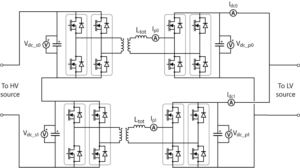
A more complex example of an input series output parallel DAB can be found in TN151.
DAB converter voltage control with phase-shift modulation
Several modulation techniques of the full-bridges can be utilized to control the power flow from one DC port of the DAB converter to the other. Some of these techniques are presented in Dual Active Bridge modulation techniques. Among these techniques, phase-shift modulation is the most common, probably due to its simplicity. It requires that the full bridges generate two-level bipolar square-wave voltages with 50% duty-cycle and power transfer is achieved by phase-shifting the voltage of one bridge against the other. The power flow can be effectively controlled by adjusting that phase shift, giving a simple control method with only one degree of freedom.
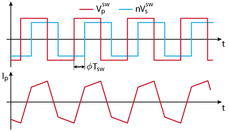
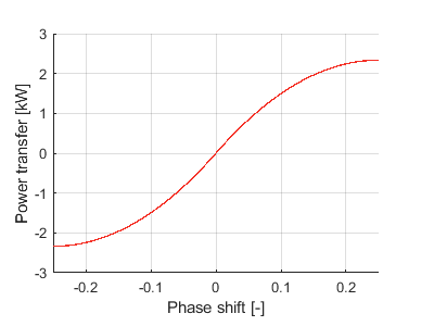
As developped in [1], the power transfer from one side to the other of the DAB converter can be expressed by the following equation and is maximal for \(\phi = 0.25\):
$$ P = \displaystyle\frac{nV_p V_s}{f_{sw}L_{tot}}\phi(1-2|\phi|) $$
Voltage control
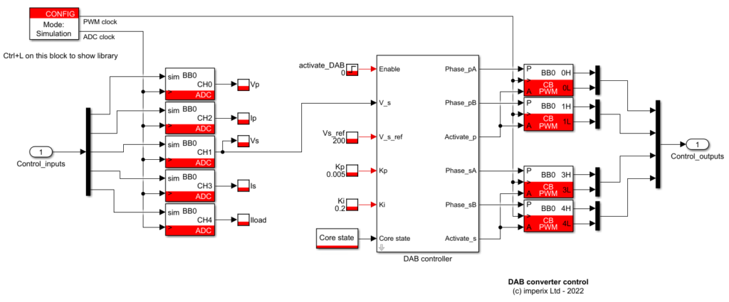
If the phase shift \(\phi\) is kept in the range [-0.25, 0.25], the power transfer curve shown above is monotonic. This means that the power transfer, and thus the secondary voltage \(V_s\) can be directly controlled with a standard PI controller. The voltage control implementation in Simulink is shown below.
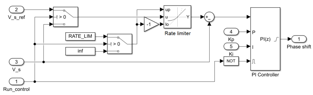
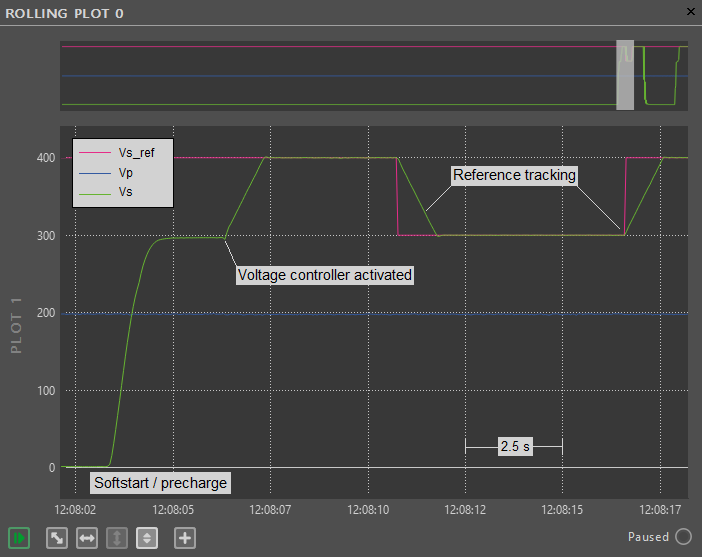
As seen later, the present control implementation has two operation modes: the start-up and the voltage control mode. A rate limiter on the voltage reference ensures a bumpless transition from the start-up mode to the voltage control mode. At the end of the start-up sequence, the voltage reference is ramped gradually from the measured voltage to the desired voltage.
Phase-shift modulation
As addressed in Dual Active Bridge modulation techniques, the carrier-based PWM modulators provided in imperix library can easily implement phase-shift modulation strategies thanks to their real-time phase parameter. The control algorithm sets the phase of each of the four legs as follows:
- In voltage control mode,
Phase_pB - Phase_pAis set 0.5 to produce two-level voltage waveforms. - The same hold for
Phase_sB - Phase_sA - The primary-to-secondary phase shift \(\phi\)
= Phase_sA - Phase_pAcontrols the power flow in the DAB converter
Soft-start of the DAB converter
When starting up the converter, a significant inrush current can flow through the bridges and the transformer, generating high stress on the components and potentially damaging them. This inrush current can be effectively mitigated by using an appropriate soft-start method.
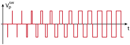
In this article, the transformer is gradually magnetized by applying a three-level voltage with a gradually increasing duty-cycle to the primary of the transformer (waveform shown below). This imposes a gradually increasing current in the transformer and charges the secondary. To ensure that the transformer current has a zero DC component, the duty-cycle of the generated pulses is increased only each two switching periods to maintain symmetry between the positive and the negative pulses.
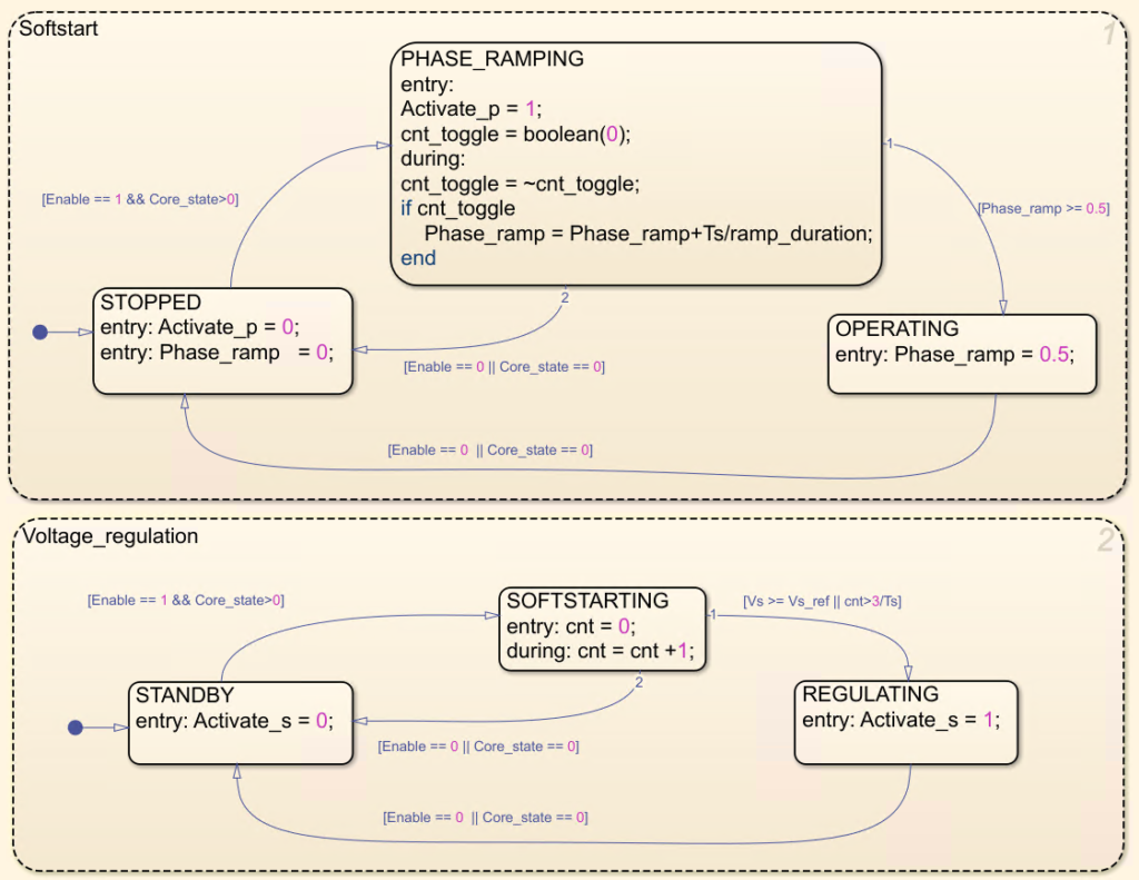
The soft-start procedure is realized with the simple state machine below, implemented with the Stateflow toolbox for Simulink. The ramping of the duty-cycle is achieved by progressively increasing the phase shift between the legs of the primary bridge. The state machine also handles the transition to the voltage control mode, as soon as the reference voltage is reached or after a given delay.
References
[1] F. Krismer, “Modeling and Optimization of Bidirectional Dual Active Bridge DC-DC Converter Topologies,” Ph.D. dissertation, ETH Zurich, 2010
DAB converter prototype
Control software
The control software is developed on Simulink, using the imperix ACG SDK toolbox. It can be downloaded using the button below:
Specifications
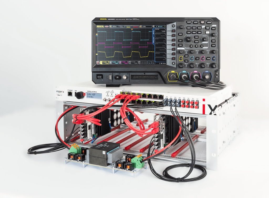
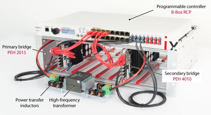
The prototype is built with the following imperix products:
- Primary full bridge: PEH 2015 (200VDC – 15ARMS – 4x IGBTs)
- Secondary full bridge: PEH 4010 (400VDC – 10ARMS – 4x IGBTs)
- Controller implementing phase-shift modulation: B-Box RCP
- Control implementation: graphical programming from Simulink using ACG SDK
The operating conditions are:
| Parameter | Value |
|---|---|
| Converter rated power \(P_n\) | 2 kW |
| Primary voltage \(V_p\) | 200 V |
| Secondary voltage \(V_s\) | 400 V |
| Transformer turn ration \(n\) | 0.5 |
| Total power transfer inductance \(L_{tot}\) | 107 µH |
| Switching frequency \(f_{sw}\) | 20 kHz |
| Load resistor \(R_{load}\) | 80 Ω, 5 A |
Test procedure
The experimental results presented here can be reproduced using the provided Simulink control model and following the procedure below:
- Configure the analog front-end of the B-Box controller so as to retrieve correctly the measured quantities and set the appropriate protection thresholds. Refer to Analog front-end configuration for more details.
- Launch the control code from the Simulink model and connect to the B-Box controller using Cockpit.
- Charge the primary DC bus by increasing progressively the source voltage to 200 V.
- Set the voltage reference
Vs_refto 400 V. - Enable the PWM outputs using the dedicated button in Cockpit as described on the Programming and operating imperix controllers page.
- Set
activate_DABto 1 to start operating the converter. - Change the voltage reference to test the reference tracking of the voltage controller
The DC voltages should behave as shown below:
Experimental results
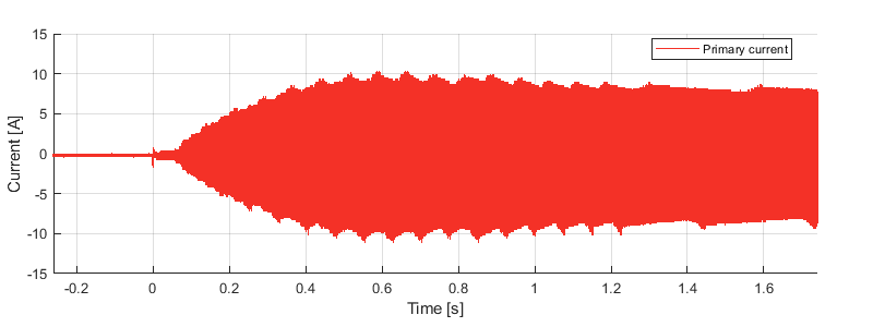
First, it is validated that the start-up procedure does not lead to excessive currents. The current scoping shown below confirms that the transformer current increases gradually without exceeding the rated value.
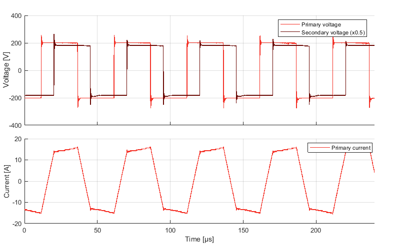
After start-up, in voltage control mode, the transformer waveforms are measured to verify the correct functioning of the phase-shift modulation strategy. As shown below, the phase shift is roughly 0.15, corresponding to a power transfer of 1.96 kW.