Table of Contents
This technical note provides an introduction to the LLC converter, which is an isolated DC-DC converter, popular in a multitude of fields. It is the first in a family of articles discussing the LLC converter:
- TN126 – LLC resonant converter for battery charging applications
- TN127 – Tank circuit design for an LLC resonant converter
The fundamental harmonic approximation is presented as a modeling technique before the operation of the LLC converter is discussed above resonance, at resonance, and below resonance.
Following that, this technical note demonstrates how to build and operate an LLC converter using imperix hardware and software, and compares the physical implementation with the theory and the simulated plant.
What is an LLC converter?
Most applications of LLC converters are characterized by the use of a resonant tank to induce a lag between the current and the voltage while exciting its isolation transformer with a near-sinusoidal current. This lagging current allows the LLC converter to operate in Zero Voltage Switching (ZVS) mode, while the sinusoidal current allows the isolation transformer to operate efficiently. On the secondary side of the transformer, rectification of the voltage can be done using diodes, or using synchronous rectifiers. This rectification occurs in Zero Current Switching (ZCS) mode. The resulting high efficiency allows the designer to increase the frequency of the LLC converter, reducing the size of all passives.
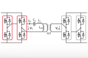
Figure 1 is a schematic of a full-bridge LLC converter. The switches on the secondary of the transformer are present to perform rectification. In a unidirectional application such as in this technical note, they can also be replaced with diodes.

Multiple modulation schemes exist for controlling LLC converters [1]. The modulation strategy considered in this technical note is Pulse Frequency Modulation (PFM). PFM changes the frequency of voltage \(V_1\), which changes the magnitude of current \(I_{Lr}\). The change of the current in the resonant tank affects voltages \(V_2\) and \(V_{load}\).
Modeling of the LLC converter
Resonant converters such as the LLC converter operate by exciting a tank circuit near its resonant frequency. As a result, a different set of assumptions have to be made, compared to the ones made for PWM converters, to derive a model that can be used to predict the behavior of the LLC converter.
The next sections discuss the Fundamental Harmonic Approximation (FHA) and how it can be used to derive a transfer function for the LLC converter when driving a resistive load [2]. An extension of this discussion for constant voltage loads can be found in TN126 – LLC resonant converter for battery charging applications
Fundamental Harmonic Approximation
Despite \(V_1\) being a square wave, when the resonant tank is excited at its resonant frequency, the resonant current \(I_{Lr}\) is sinusoidal with negligible harmonic content. As a result, FHA supposes that \(V_1\) can be approximated by considering only its fundamental harmonic when the resonant tank is excited near its resonant frequency. Consequently, power transfer through the resonant tank and the transformer can be analyzed and the relationship between \(V_2\) and \(V_1\) can be derived.
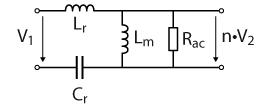
The derivation of \(\frac{V_2}{V_1}\) requires the replacement of the full-bridge rectifier and \(R_{load}\) with an equivalent resistance \(R_{ac}\). Due to the FHA, it is assumed that the current flowing through the transformer is purely sinusoidal. Therefore, by equating the DC component of the rectified current flowing through the resistor with the load current, an expression can be found for \(R_{ac}\) [2].
Note that \(R_{ac}\) is referred to the primary side of the isolation transformer.
\begin{equation}
R_{ac} = \frac{n V_{2_{RMS}}}{\frac{1}{n} I_{2_{RMS}}} = \frac{8n^2}{\pi^2} R_{load}
\end{equation}
Transfer function of the LLC converter
Having referred the load to the primary side, the resonant tank, shown in Figure 2, can be analyzed:
A frequency-dependent gain function can be defined for the circuit in Figure 2 [3].
$$
V_2 = \frac{V_1}{n} \frac{-\omega^2 R_{ac} L_m}{R_{ac} (\frac{1}{C_r}-\omega^2(L_m+L_r)) + j \omega L_m (\frac{1}{C_r}-\omega^2 L_r L_m)}
$$
This function can be normalized after making the following substitutions:
$$
\begin{align}
L_n &= \frac{L_m}{L_r} \\
\\
\omega_n &= \frac{\omega}{\omega_r} \\
\end{align}
$$
$$
\begin{align}
\omega_r &= \frac{1}{\sqrt{L_r C_r}} \\
\\
Q &= \frac{\sqrt{\frac{L_r}{C_r}}}{R_{ac}} \\
\end{align}
$$
- \(Q\) is defined as the quality factor of the circuit. It is the ratio between the characteristic impedance \(\sqrt{\frac{L_r}{C_r}}\) , and \(R_{ac}\)
- \(L_n\) is defined as the normalized inductance. It is the ratio between the magnetizing inductance and resonant inductance.
- \(\omega_n\) is the normalized switching frequency of the LLC converter.
- \(\omega_r\) is considered the resonant frequency of the LLC converter even though the location of the peak gain of the LLC converter can vary based on operating conditions.
The equation, after making the relevant substitutions, is shown below. It has been rearranged to show the gain of the resonant tank.
$$
\frac{V_2}{V_1} = \frac{1}{n} \frac{-\omega_n^2 L_n}{1-\omega_n^2 (L_n + 1) + j L_n \omega_n Q (1 – \omega_n^2)}
$$
LLC converter parameter selection
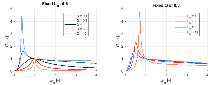
The influence of the main design parameters, namely \(L_n\) and \(Q\), can be analyzed from the graphs below.
Quality factor \(Q\)
The left plot in Figure 3 shows how the gain curve of the LLC converter varies as the \(Q\) factor is modulated for a fixed \(L_n\).
By definition, a larger \(Q\) factor means that the characteristic impedance of the resonant tank is considerably larger than the loading effect imposed by \(R_{load}\). Therefore, a larger \(Q\) factor implies that the resonant current magnitude will not greatly change as the load impedance varies. This is advantageous in ensuring that the circulating current in the resonating tank stays within desired limits during operation.
However, due to the same reason, a high \(Q\) factor limits the maximum achievable gain (shown in Figure 3). The designer will therefore have to balance the effect of increased circulating current in the resonant tank versus the ability to reach the required peak gain, which is often a design constraint.
Note that, for all quality factors, the gain at \(\omega_n = 1\) is always 1. This is an interesting property of the LLC converter as the insensitivity to changes in the load impedance at this operating point allows the LLC converter to have excellent transient performance when operating at resonance.
Normalized inductance \(L_n\)
The right plot in Figure 3 shows how the gain curve for the LLC converter changes for various normalized inductances.
If the \(Q\) factor and \(\omega_r\) are considered fixed, then a larger \(L_n\) implies that the transformer part of the LLC converter’s resonant tank has a larger magnetizing inductance \(L_m\). Therefore, when comparing two designs operating at resonance, the LLC converter with a larger \(L_n\) will have less magnetizing current due to its transformer. The reduction in this current increases the efficiency of the LLC converter at this operating point.
On the other hand, an increased \(L_n\) results in a decrease in the dynamic range of the possible gain of the resonant tank. Additionally, even if the required gains are achievable in two competing designs, the LLC converter with the larger \(L_n\) will require a greater shift in operating frequency to change the gain of the LLC converter.
The larger required change in frequency affects all aspects of LLC converter design:
- a lower minimum operating frequency will require larger filters to ensure the current ripple remains within specification
- a higher maximum operating frequency will result in higher switching losses and the typical EMC concerns associated with higher-frequency switching
- a large deviation in frequency would complicate the design of the magnetics as they would be operating in a larger range of frequencies
As a result, just as with the \(Q\) factor, the designer will have to balance the desire to reduce the converter magnetizing current with the disadvantages that a large \(L_n\) creates.
The LLC converter is often designed iteratively to ensure that all constraints are effectively met.
Operation of the LLC converter
Operation at resonance (\(\omega_n = 1\))
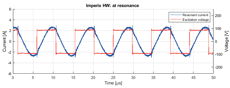
When operating the LLC converter at resonance, the gain of the resonant tank is one. Furthermore, the ZVS (at turn-on of the primary switches) & ZCS (for the rectification diodes) conditions are fulfilled and the resonant tank current is sinusoidal.
Figure 4 shows a plot from a simulated LLC converter operating at resonance. The excitation voltage is plotted alongside to show the switching transitions.
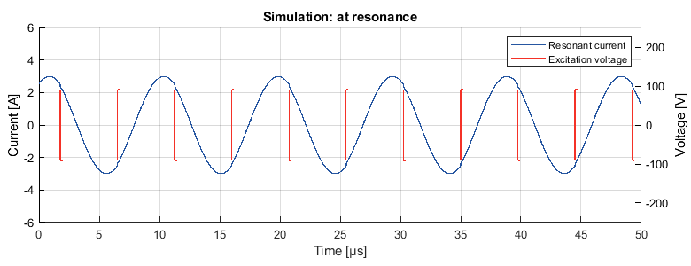
The reduced switching losses, coupled with the reduced losses in the magnetics due to the sinusoidal current, make this operating point the most efficient. The high efficiency at this operating point has given rise to converter topologies where the LLC converter remains at resonance at all times [4].
Operation above resonance (\(\omega_n > 1\))
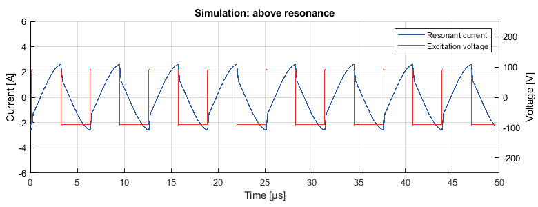
When operating the LLC converter above resonance, the gain of the resonant tank is below 1. As the resonant tank impedance is always inductive above the resonant frequency, ZVS on the primary side switches is guaranteed at turn-on.
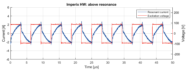
Operating above resonance is characterized by a tank current like the one shown in Figure 5 below. The current begins to naturally oscillate at \(\omega_r\) before the earlier switching changes the shape of the current as shown in the figure.
Operation below resonance (\(\omega_n < 1\))
When operating the LLC converter below resonance, the gain of the resonant tank can be either above or below 1 depending on the frequency of operation.
When switching the LLC converter below the resonant frequency, while remaining in the ZVS region, the shape of the current is as shown in Figure 6.
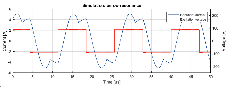
As mentioned for other operating modes, the current starts to naturally oscillate at \(\omega_r\). In this case, the later switching, compared to resonant operation, results in the magnetizing inductance of the transformer maintaining the polarity of the current until the next switching instance.
When switching below resonance, the LLC converter can operate either in ZVS mode or in ZCS mode, depending on the operating frequency. The boundary between the ZVS mode operating region and the ZCS mode operating region can be found by substituting the expression below into the equation of the resonant tank gain.
$$
Q = \sqrt{\frac{1}{(1-\omega_n^2)L_n} – \frac{1}{\omega_n^2 L_n^2}}
$$
Figure 7 shows the boundary between the two areas, and how the LLC converter gain is split between the ZVS mode region and the ZCS mode region.
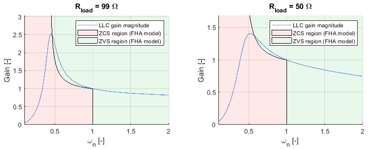
In the case of high-frequency converters such as the LLC converter, generally, the switch of choice tends to be Si(C) MOSFETs or GaN HEMTs. For these devices, turn-on losses are greater than turn-off losses, therefore choosing the ZVS mode of operation is favorable because the ZVS mode results in no turn-on losses.
Since the ZVS/ZCS boundary crosses close to the peak of the gain-frequency plot, and there is a desire to remain in the ZVS mode zone, the lower limit of the switching frequency is limited to the frequency corresponding to the ZVS boundary.
LLC converter prototype example
Imperix products can be used to easily implement a laboratory-scale prototype of the LLC converter. Figure 8 shows a possible implementation, made using the following products:
- a B-Box RCP controller
- 2x PEB 8024 are used to create a SiC H-bridge that is capable of switching at up to 200 kHz
- 2x PEB 4050 are used, without any gate signals, as diodes since the IGBT technology has excellent body diodes in comparison to the SiC-based modules
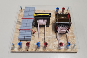
- A custom resonant tank (as discussed in TN127), with the following parameters:
- Lr = 21 µH
- Lm = 90 µH
- Cr = 110 nF
- A transformer with n = \(\frac{8}{9}\)
- A resistive load of either 99 Ω or 50 Ω
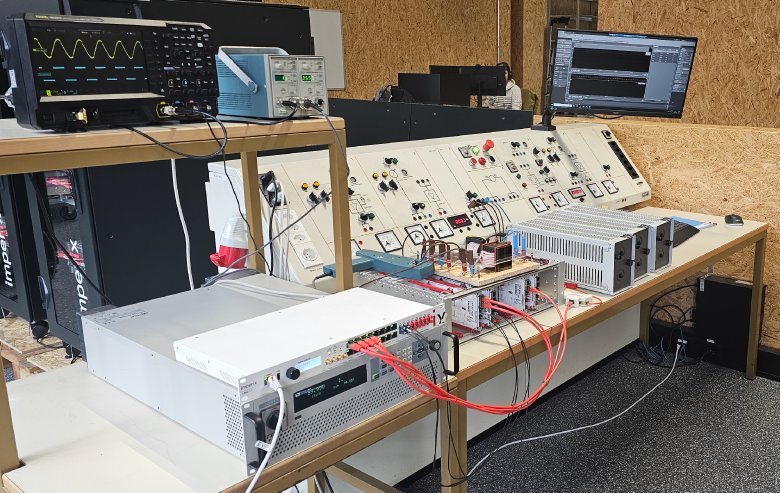
Experimental setup

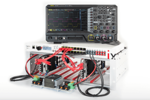
Figure 9 shows a picture of the setup used to validate the provided Simulink file. The analog measurements and gate-driving optical fibers are wired such that they match the example model that can be downloaded below.
Practical advice
- Since the LLC converter is a resonant converter that can be switched faster than the control frequency, it is essential that the hardware protections on the B-Box are correctly set to protect the equipment
- Imperix modules require the de-rating of allowable RMS current as a function of the switching frequency. The derating curves can be found in the datasheets
- The ratings of the capacitor bank in the resonant tank must be carefully observed to ensure that it can withstand both the maximum voltage across the capacitors and the maximum RMS current flowing through them.
- The recommendations outlined in TN181 should be followed to maximize safety when performing experiments in the lab.
Simulink model

Installing the imperix block set from the ACG SDK gives the user access to custom blocks which facilitate using Simulink to program the B-Box. Figure 10 shows how the Simulink block set is used to implement the open loop control of the LLC converter in the downloadable file below.
When controlling the LLC converter using PFM, the following blocks from the block set are essential:
- Configuration block: CLOCK_0 is set to 20 kHz
- ADC block
- CB-PWM generator: 2 blocks are needed to drive the primary-side H-bridge, with a duty ratio of 0.5 and a 0.5 offset in phase
- Probe block
- The signals plotted in Cockpit will have the sampling frequency configured in the configuration block (using CLOCK_0). An external measurement using higher bandwidth equipment will be required to capture \(V_1\) and \(I_{L_r}\)
- Tunable parameter
- The ability to set limits in the tunable parameter is particularly useful in the case of the LLC converter because it ensures that the frequency of the converter remains within the ZVS mode limits
For additional information regarding the soft-start state machine included in the model, additional information can be found in the following article: TN115 – DAB converter control using phase-shift modulation.
CLOCK block
Most imperix examples use the clock output from the configuration block to drive both the ADC and CB PWM blocks. However, to implement PFM, a separate clock block (CLOCK_1) must be inserted into the model. There, by changing its configuration, its frequency input can be enabled.
Experimental results
As expected from the LLC converter, when exciting the resonant tank at its resonant frequency (\(\omega_n = 1\)), the current is sinusoidal, as can be seen in Figure 11. It is very similar to the simulated current and voltage in Figure 4.
As shown in Figure 12, measuring the resonant current of the LLC converter above resonance shows a current waveform very similar to the simulated current in Figure 5.
As shown in Figure 13, measuring the resonant current of the LLC converter below resonance shows a current waveform very similar to the simulated current in Figure 7.
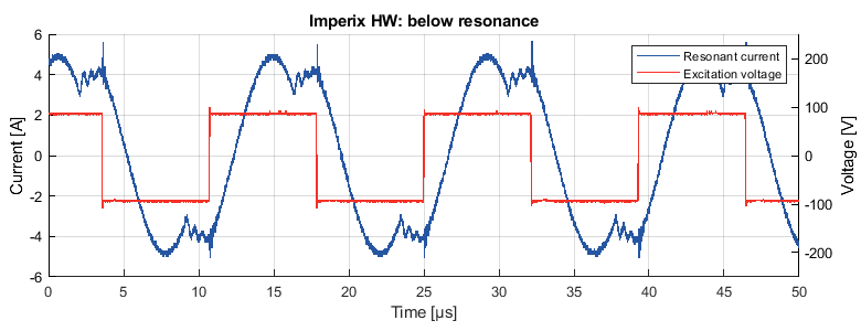
Figure 14 compares using the FHA model of the LLC converter for gain estimation with a physical measurement.
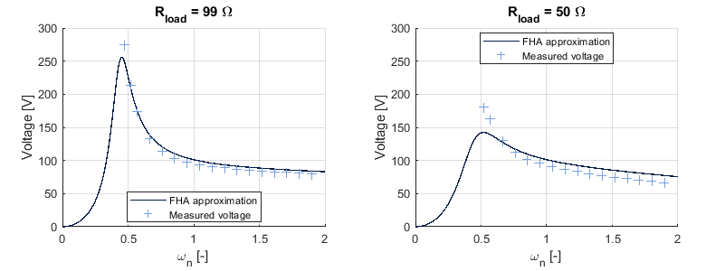
Calculating the gain using the FHA model underestimates the gain near its peak, and overestimates the gain at higher frequencies. The theoretical curve should match the physical measurement at \(\omega_r\) (or \(\omega_n = 1\)), however since the series resistance and other non-idealities were not accurately modeled, the actual crossover point occurs at a lower switching frequency.
While the results in Figure 14 show that there are differences between the predicted output voltage and the measured output voltage, FHA is still reasonably accurate for designing an LLC converter. Additionally, other modeling techniques for the LLC converter exist even if the accuracy of the FHA prediction is not sufficient for a given application [5].
References
[1] Y. Wei, Q. Luo and A. Mantooth, “Overview of Modulation Strategies for LLC Resonant Converter,” in IEEE Transactions on Power Electronics, Oct. 2020
[2] R. W. Erickson, D. Maksimović, Fundamentals of Power Electronics, 3rd ed., Springer Cham, Cham, Switzerland, 2020, pp. 940–945.
[3] C. Adragna, LLC Resonant Converters: An Overview of Modeling, Control and Design Methods and Challenges, now, 2022. pp. 160–168.
[4] Q. Liu, Q. Qian, B. Ren, S. Xu, W. Sun and L. Yang, “A Two-Stage Buck–Boost Integrated LLC Converter With Extended ZVS Range and Reduced Conduction Loss for High-Frequency and High-Efficiency Applications,” in IEEE Journal of Emerging and Selected Topics in Power Electronics, Feb. 2021
[5] J. F. Lazar and R. Martinelli, “Steady-state analysis of the LLC series resonant converter,” in Proc. of APEC 2001, Anaheim, CA, USA, 2001, pp. 728-735 vol.2


