Table of Contents
This example introduces the working principles of a three-phase voltage source inverter and presents a simple technique to generate alternating currents in an open-loop manner, using the imperix ACG SDK on Simulink or PLECS.
As such, this simple example can serve as an introduction to the imperix tools, but also as a reference model for performing the first set of tests on new equipment, or simply as a control code for grid-forming inverters or UPS inverters.
Downloads
The following files contain the implementation of this application in the MATLAB Simulink environment using the ACG SDK. As always, the same model can be used to simulate the behavior of the system in an offline simulation and generate code for real-time execution of the control algorithm on an imperix controller.


Working principle of a voltage source inverter
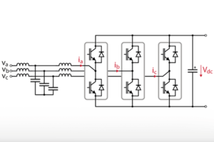
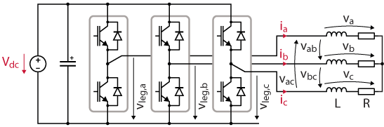
This application considers a three-phase two-level voltage source inverter (VSI) connected to a passive RL load, as depicted above. The inverter produces three sinusoidal load currents with configurable amplitude.
The variables highlighted in red are measured and sent to the controller for monitoring and protection purposes.
Modulation signals and duty cycles
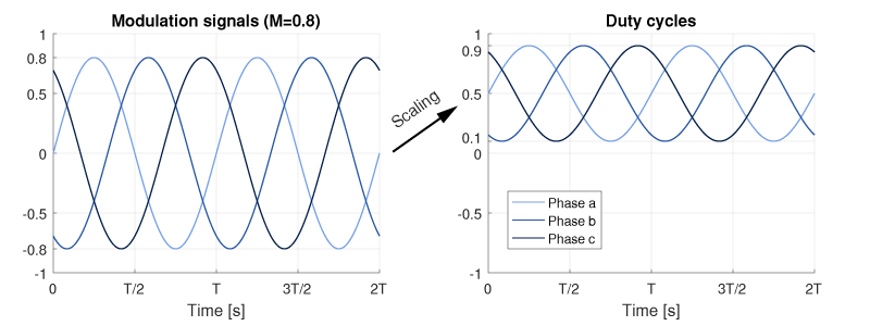
Three sinusoidal modulation signals \(m_{abc}\) are generated, with a frequency \(f\) and an amplitude \(M\). These modulation signals will produce fundamental phase voltages with an amplitude \(V = M V_{dc}/2\), as developed later.
$$\left\{\begin{array}{l} m_a = M \sin(2\pi f t)\\ m_b = M \sin\left(2\pi f t-2\pi/3\right)\\ m_c = M \sin\left(2\pi f t+2\pi/3\right) \end{array}\right.$$
As the Carrier-Based PWM modulators of the B-Box RCP controller use a PWM carrier varying between 0 and 1, the modulation signals have to be scaled to fit in the range [0, 1], as depicted below. The duty-cycles are computed as follows:
$$d_i = \cfrac{m_i}{2}+\frac{1}{2} \quad \text{for } i=a,b,c$$
Phase and line-to-line voltages
Applying the duty-cycles \(d_i\) to each phase leg will produce the following fundamental leg voltages:
$$\left\{\begin{array}{l} \langle v_{leg,a} \rangle = V_{dc}\cdot d_a=\cfrac{V_{dc}}{2}M \sin(2\pi f t)+\cfrac{V_{dc}}{2}\\ \langle v_{leg,b} \rangle = V_{dc}\cdot d_b=\cfrac{V_{dc}}{2}M \sin(2\pi f t-2\pi/3)+\cfrac{V_{dc}}{2}\\ \langle v_{leg,c} \rangle = V_{dc}\cdot d_c=\cfrac{V_{dc}}{2}M \sin(2\pi f t+2\pi/3)+\cfrac{V_{dc}}{2} \end{array}\right.$$
The fundamental three-phase line-to-line voltages are hence:
$$\left\{\begin{array}{l} \langle v_{ab}\rangle= \langle v_{leg,a}\rangle – \langle v_{leg,b}\rangle = \cfrac{\sqrt{3}V_{dc}}{2}M\cos\left(2\pi f t-\pi/3\right)\\ \langle v_{bc}\rangle = \langle v_{leg,b}\rangle – \langle v_{leg,c}\rangle = \cfrac{\sqrt{3}V_{dc}}{2}M\cos\left(2\pi f t-\pi\right)\\ \langle v_{ca}\rangle = \langle v_{leg,c}\rangle – \langle v_{leg,a}\rangle = \cfrac{\sqrt{3}V_{dc}}{2}M\cos\left(2\pi f t+\pi/3\right) \end{array}\right.$$
From the last result, we can retrieve the expression of the fundamental phase voltages (i.e. line-to-neutral):
$$\left\{\begin{array}{l} \langle v_a\rangle = \cfrac{V_{dc}}{2}M\sin\left(2\pi f t\right)\\ \langle v_b\rangle = \cfrac{V_{dc}}{2}M\sin\left(2\pi f t-2\pi/3\right)\\ \langle v_c\rangle = \cfrac{V_{dc}}{2}M\sin\left(2\pi f t+2\pi/3\right) \end{array}\right.$$
This confirms that the generated \(m_i\) correspond to the phase voltages, normalized by \(V_{dc}/2\).
This can be illustrated by comparing the modulated signal \(m_a\) with the fundamental \(\langle v_a \rangle\), superimposed on the switched voltage \(v_a\).
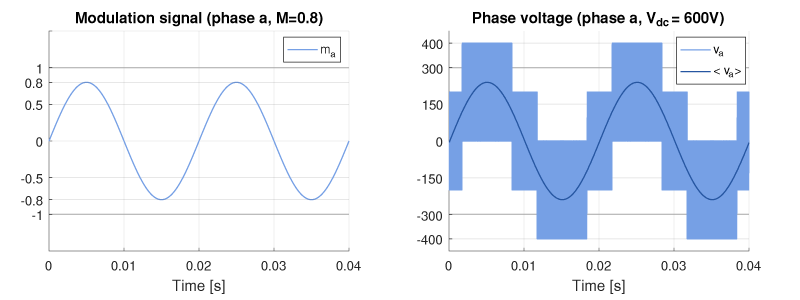
As a side note, the switched voltage in the right figure takes the discrete values \(2V_{dc}/3\), \(V_{dc}/3\), \(0\), \(-V_{dc}/3\), and \(-2V_{dc}/3\), which are the 5 different phase voltage values that the 8 switching states of an inverter can produce.
Load currents
The phase (i.e. load) currents can be derived from the phase voltage equations. In particular, their RMS values can be controlled with the modulation index \(M\), since:
$$I_{a,RMS} = I_{b,RMS} = I_{c,RMS} = \cfrac{\sqrt{2}}{4}\cfrac{MV_{dc}}{\sqrt{R^2+(2\pi f L)^2}}$$
Control implementation for a voltage source inverter
Duty cycle generation
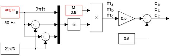
The duty cycles are generated in an open-loop manner with the expressions of \(m_i\) and \(d_i\) presented above. A sinewave generator is implemented using an “angle” block from imperix library, which outputs directly the argument \(2\pi f t\). The Simulink blocks used to compute the duty cycles are shown below.
Pulse width modulation (PWM)
The present application uses Carrier-based PWM (CB-PWM) modulators to generate the gating signals of the six switches from the computed duty cycles \(d_i\) and uses a triangular carrier. Each CB-PWM block generates the high- and low-side gating signals for a specific phase leg.
A dead time of 1 µs is added between the ‘on’ states of each pair of complementary signals to avoid destructive shoot-through during the operation of the real inverter. In simulation, the dead time is also modeled and the slight waveform distortion that it brings can be observed in simulation results.
The behavior of these blocks in simulation and code generation modes is further explained in CB-PWM – Carrier-based PWM.
Analog measurements
In this application, the phase currents and the DC bus voltage are measured and sent back to the controller’s analog inputs. As no closed-loop control is implemented, these measured quantities are used for monitoring purposes only. In most applications, however, these quantities are required by the control algorithm to compute the duty cycles in a closed-loop manner.
The analog measurements are retrieved by the control code with ADC blocks. The behavior of these blocks in simulation and code generation modes is detailed in ADC – Analog data acquisition.
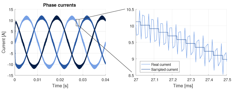
The sampling phase can be configured in the CONFIG block. This application uses a phase of 0.5 and triangular PWM carriers, to ensure that the sampling is always done in the middle of the current ripples. This configuration gives naturally access to an averaged value of each measured currents, without the addition of any filter and its inevitable delay.
The figure below shows a comparison between the actual phase current (computed by the simulation plant model) and its sampled value to illustrate that the sampled current corresponds to the average of the current ripples.
Further details on the offline simulation capabilities of ACG SDK are presented in the following pages: