Table of Contents
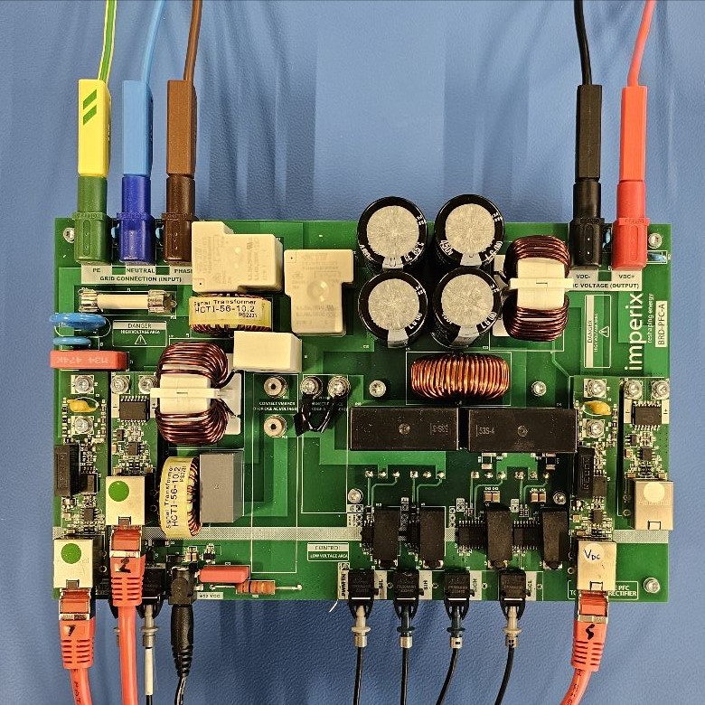
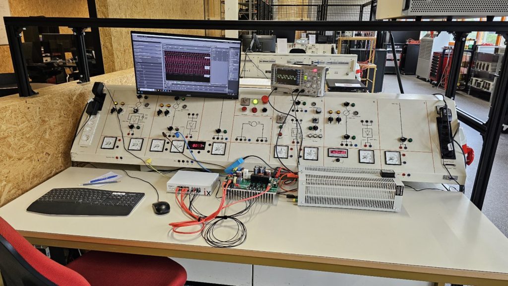
This article introduces the concept of power factor correction (PFC) using a single-phase totem-pole PFC rectifier as an example. The theory presented is then validated using a custom 1.2 kW prototype (displayed in Figure 1) controlled using imperix hardware.
Introduction
Although reactive power does no mechanical work, the grid must support the apparent power drawn by all users. Therefore, the grid operator sets constraints on the power factor for loads connected to the grid to protect their infrastructure. Ideally, loads connected to the grid should emulate a resistor, consuming only active power. The nature of most loads (motors, non-linear loads, etc.) requires the inclusion of an Active Front End, of which the totem-pole PFC rectifier is a single-phase example.
Power Factor is defined as the following equation:
$$ PF = \frac{P}{S} $$
If sinusoidal voltages and currents are assumed, then the power factor can also be defined as:
$$ PF= \cos\phi $$
where \(\phi\) is the phase shift between the voltage and current.
However, since the grid current is often not perfectly sinusoidal, the equation above is adapted to the following [1]:
$$ PF = \frac{\cos\phi}{\sqrt{1+ {THD}^2}} $$
where THD is the total harmonic distortion measured in the grid current, assuming an ideal, stiff grid voltage.
Power factor correction (PFC) is the name given to the concept behind bringing the power factor as close to 1 as possible. The power factor can be improved using two distinct families of solutions:
- Passive PFC improves the power factor by using passive components at the AC input [2].
- Active PFC improves the power factor using a switching power converter. It is, therefore, usually more compact than passive PFC. A power factor of over 99% is achievable using active PFC [2].
Totem-pole PFC and boost PFC (diode rectifier + boost converter) are two common topologies used to correct the power factor in single-phase applications. In three-phase systems, PFC is usually implemented by an Active Front End.
Totem-pole PFC rectifier topology
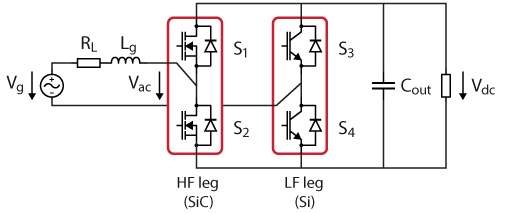
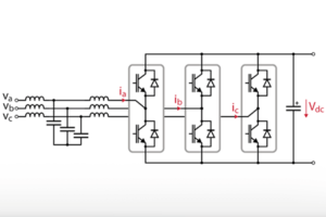
Figure 2 shows the topology of a totem-pole PFC rectifier, which is almost identical to that of a single-phase rectifier. The principal difference between the two converters is the modulation strategy employed and, as a result, the type of switches utilized.
The totem-pole rectifier employs a high-frequency leg and a line-frequency leg, whereas the single-phase rectifier switches both legs at the same frequency. Subsequently, the totem-pole PFC rectifier can use slower switching bipolar devices with lower conduction losses than the regular rectifier in the line-frequency leg. As a result, the totem-pole rectifier can be comparatively more efficient.
Switching conduction modes
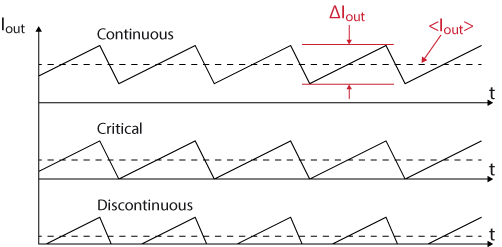
The totem-pole PFC rectifier is able to operate in three different switching conduction modes, illustrated in Figure 3. (further details can be found in TN100 – Step-down buck converter):
- Continuous Conduction Mode (CCM) produces low conduction and inductor core losses, but hard switching is used, which implies high energy losses.
- Critical Conduction Mode (CRM) operates in zero voltage switching (ZVS) conditions, but the peak current is limited to twice the average current.
- Discontinuous Conduction Mode (DCM) involves lower efficiency than the previous cases due to the high peak current, although zero current switching (ZCS) is possible.
Totem-pole PFC rectifier modulation
The modulation strategy will vary depending on the selected switching conduction mode. In this article’s hardware example, CCM was selected.
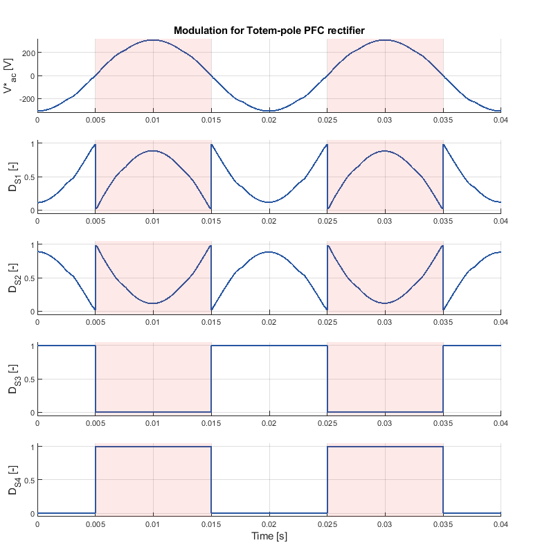
Figure 4, below, illustrates the duty ratio of the four switches for a given Vac reference, providing a visual aid to the discussion regarding totem-pole PFC rectifier modulation.
Low-frequency leg
The low-frequency leg of the totem-pole PFC rectifier can be considered a 50 Hz synchronous rectifier.
Referring to the labels in Figure 2, switch S3 should be switched low during the positive half-cycle of V*ac, and switched high during the negative half-cycle of V*ac, as shown in Figure 4. Switch S4 is complementary to switch S3. Due to its dependence on the zero-crossing of V*ac, the modulation strategy employs a direct output pulse width modulator.
It is noteworthy that the inductance of the totem-pole rectifier may introduce a non-negligible phase shift between the grid voltage, Vg, and the output voltage of the inverter, Vac. As such, the synchronous rectification should be synchronized to the polarity of V*ac rather than Vg.
While it would remain functional if the low-frequency leg were replaced with diodes, the implementation with switches also allows for bidirectional operation on top of the aforementioned superior efficiency.
High-frequency leg
The high-frequency leg of the totem-pole PFC rectifier is modulated to produce the desired output voltage Vac.
Similarly to a bidirectional buck converter operating in CCM, the duty ratio for the S1 in Figure 2 is computed using the following equation:
$$ D = \frac{V^*_{ac}}{V_{dc}} $$
However, when the polarity of Vac is negative, switch S1 and switch S2 effectively swap positions if the totem-pole PFC rectifier is modeled as a bidirectional buck converter. Therefore, to maintain the same relationship, the duty ratio of switch S1 when Vac is negative is computed as:
$$ D = 1 – \frac{V^*_{ac}}{V_{dc}} $$
In all cases, switch S2 is complementary to switch S1.
Figure 4 illustrates the duty ratio during the operation of the totem-pole PFC rectifier. As the goal of the converter is to maintain a sinusoidal current in phase with the grid voltage, V*ac also follows a sinusoidal reference.
To remain in CCM (and minimize the current ripple in the inductor), the HF leg is switched at high frequencies using a carrier-based pulse-width modulator.
Control of single-phase totem-pole PFC rectifier
The control objective of a PFC converter is to control the output DC voltage at a given setpoint while maintaining a power factor of one. This is achieved using cascaded voltage control: the inner loop controls the grid current while ensuring that the power factor is equal to one, and the outer loop controls the DC bus voltage.
The control strategy implemented assumes the same plant models as in TN108 – cascaded voltage control.
Because the inner loop of the totem-pole PFC rectifier is controlling the grid current, a PR controller tuned to 50 Hz can be used to minimize the error between the grid current and its setpoint. Since it is tuned assuming its output is the voltage across the inductor, Vac is calculated by summing Vg to its output.
To ensure that the output of the outer loop PI controller results in a current request in phase with the grid current, a PLL and an inverse Park transform are utilized to convert the DC output of the PI controller into an AC current request for the PR controller. Other methods to generate the AC current reference exist, some of which do not require a PLL or inverse Park transform [4].
Cascading the two controllers results in the overall control scheme visualized in Figure 5:
Since the totem-pole PFC rectifier is a single-phase converter, 100/120 Hz power pulsation is inevitable because zero power is transferred from the grid to the load when Vg equals zero. The control may not be effective if it is designed without taking the power pulsation into account.
Tuning the inner loop
Given that:
- the plant model is valid, given that the controller bandwidth is much smaller (<10%) than the switching frequency,
- the main frequency of interest is 50 Hz,
- a high bandwidth current controller is desired,
the targeted bandwidth of the controller is ~5 kHz (~30000 rad/s), with maximum gain at 50 Hz (~300 rad/s).
One method of tuning the controller is graphically using the Bode plots of the loop transfer function T(s) [1]:
$$ T(s) = G_{controller}(s)*G_{plant}(s)*H_{fb}(s)$$
where Hfb(s) can be assumed to be 1 given that the sensors have sufficient bandwidth with a flat gain.
The control bandwidth and stability can be graphically determined from the cross-over frequency and phase margin of T(s).
The first step is to assume Gcontroller(s) equals 1 to visualize how the controller needs to modify T(s) to achieve the controller objectives.
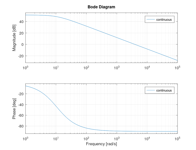
Assuming the parameters from Table 1, the Bode plot of Gplant(s) for the inner loop is shown in Figure 6 below.
The cut-off frequency of T(s) is adapted using the proportional term of the PR controller. Since the gain of Gplant(s) in Figure 6 at 30000rad/s is ~-20 dB, introducing a Kp of 10 increases the gain by 20 dB and shifts the cut-off frequency to 30000rad/s (~5 kHz).
To reach the objective of having the peak gain be at 50 Hz, a PR controller tuned to 50 Hz with a window width of 2 Hz is used. A window width of 2 Hz is used since the grid frequency may fluctuate slightly. A larger window width also provides additional damping to the PR controller, limiting overshoot.
Referring to TN110 – PR controller, it is estimated that a Kr of 1500 would provide an appropriate response for this application.
The Bode plot of T(s) including the designed controller, shown in Figure 7, is used to validate that the designed control has the expected bandwidth and is stable. Note that a delay of 1.5 switching periods and the discrete nature of the controller were also taken into account.
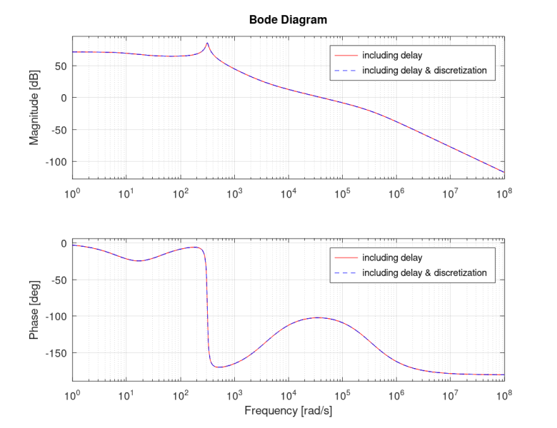
Referring to Figure 7, the current control has a bandwidth of 38400rad/s (~6.4 kHz) with a phase margin of 78 degrees. Since a bandwidth of 6.4 kHz is close to 5 kHz, and there is sufficient phase margin, the designed controller is considered to have met the control objectives.
Tuning the outer loop
The goal for this control loop is to:
- have maximum gain at DC
- reject the inevitable power ripple at 100 Hz.
One solution to reject the power pulsation is to limit the outer loop bandwidth below 100 Hz. Selecting a bandwidth of ~10 Hz (~60 rad/s) ensures that the controller does not act on the power pulsation.
A Kp of 0.1 and a Ki of 2 are selected following a similar procedure as for the inner loop. These parameters shift the cut-off frequency to 10 Hz while increasing the DC gain.
As before, the controller performance is validated using the Bode plot shown in Figure 8.
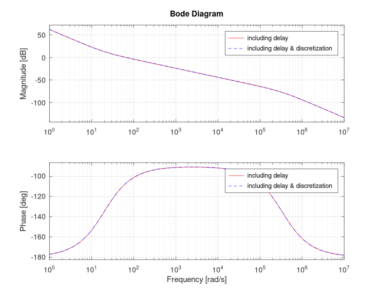
Referring to Figure 8, the voltage control has a bandwidth of 64.2 rad/s (~10.7 Hz) with a phase margin of 73 degrees. Since the controller achieves the targeted bandwidth and sufficient phase margin, the designed controller is considered to have met the control objectives.
Totem-pole PFC converter hardware implementation
The demonstrator designed for this article, shown in Figure 9 above, is a custom totem-pole PFC rectifier based on a slightly modified reference design provided by GaN Systems [5]. The design was adapted to be able to control the device using the B-Box Micro. The parameters of the modified prototype are highlighted in Table 1 below:
| Parameter | Value | Unit |
| Vin, tested | 230 | Vrms |
| VDC, tested | 350 | V |
| Pmax, tested | 1300 | W |
| fsw, op | 50 | kHz |
| Lg | 250 | µH |
| RL | 2.7 | mΩ |
| Cout | 1.56 | mF |
Controlling the converter using the table-top B-Box Micro comes with a couple of key advantages compared to other solutions:
- The controller can be programmed using Simulink or PLECS.
- The controller has µs level configurable protection triggered by the analog inputs
- The controller provides ±15 V supply for the analog sensors
- The Cockpit real-time monitoring software simplifies testing the control and extracting the results
- The controller is easy to isolate from the device under test
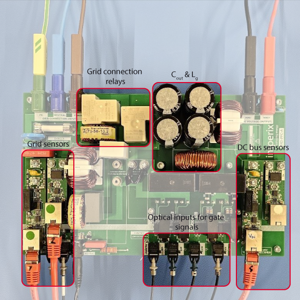
To best take advantage of these features, alongside the power stage, the following circuits were implemented on the prototype board:
- Isolated gate drivers with an optical transceiver as the input
- Isolated relay drivers with an optical transceiver as the input
- Regulated power supplies assuming an external isolated 12 V input
- Modular isolated voltage and current sensor, using an RJ45 connector as the IO
A labeled close-up image of the totem-pole PFC rectifier is shown in Figure 10.
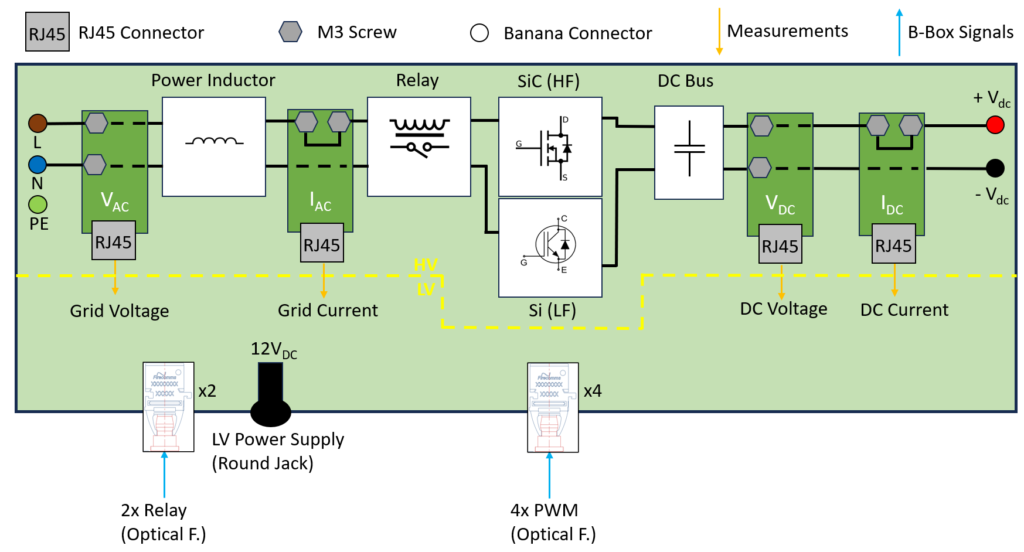
For additional clarity, Figure 11 illustrates the converter and its interfaces diagrammatically.
Totem-pole PFC rectifier control implementation
Using the ACG SDK, the cascaded voltage control and modulation strategy discussed above can be quickly implemented in Simulink (or PLECS if preferred). Figure 12 below shows an overview of the control implemented.
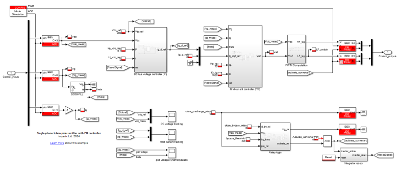
The modulation strategy described in section 3 is implemented in the model as shown in Figure 13:
The Simulink file can be downloaded using the button below:
Once designed and simulated, the control can be easily converted to run-time code using the code generation feature of ACG SDK.
Experimental results
The grid voltage and current, measured from the sensors on the custom board, are shown in Figure 14.
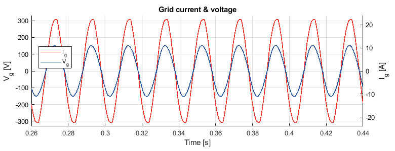
It can be seen that the totem-pole PFC rectifier maintains the grid voltage and grid current in phase. The \(\cos\phi\) is equal to 0.9991. In addition to ensuring that the voltage and current are in phase, a totem-pole PFC rectifier must also minimize the THD in the current waveform to maximize the power factor. A visual understanding of the distortion in the current waveform can be obtained by performing an FFT, shown in Figure 15.
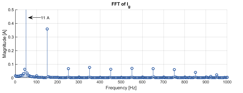
The amplitude of the main harmonic (11 A) is off the scale to better visualize the higher-order harmonics.
A THD of 3.5% is computed from the current waveform in Figure 14. Together with the \(\cos\phi\), the overall power factor is 99.86%.
Earlier in the article, it was discussed that the bandwidth of the outer loop controller is reduced to approximately 10 Hz, so the controller does not attempt to correct the inevitable power pulsation. The low THD in the results above demonstrates that the controller intervenes minimally to compensate for the power pulsation. However, this tuning increases the settling time of the DC voltage.
Figure 16 shows the totem-pole PFC rectifier’s voltage transient response during a load step from 143 Ω to 96 Ω.
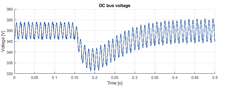
Due to the slow response of the outer voltage control loop, the voltage sags considerably before returning to its steady-state value. While such a response may be considered unacceptable depending on the application, the totem-pole PFC rectifier is usually cascaded with an additional converter in series, such as an LLC converter in an On-board charger (AN010). A current feedforward term in the control loop is demonstrated in AN010 to mitigate the slow response from the voltage control loop.
References
[1] R. W. Erickson, D. Maksimović, Fundamentals of Power Electronics, 3rd ed., Springer Cham, Cham, Switzerland, 2020.
[2] O. Garcia, J. A. Cobos, R. Prieto, P. Alou and J. Uceda, “Single phase power factor correction: a survey,” in IEEE Transactions on Power Electronics, May 2003
[3] Bosheng Sun, “How to reduce current spikes at AC zero-crossing for totem-pole PFC ” Texas Instruments in Analog Applications Journal, 2015
[4] B. Su, J. Zhang and Z. Lu, “Totem-Pole Boost Bridgeless PFC Rectifier With Simple Zero-Current Detection and Full-Range ZVS Operating at the Boundary of DCM/CCM,” in IEEE Transactions on Power Electronics, Feb. 2011
[5] GaN Systems, Appl. Note GS1200BTP-EVB – rev 190923, “High-Efficiency 1.2 kW GaN Based Bridgeless Totem-Pole PFC”, 2019


