Table of Contents
This technical note introduces the working principle of an Active Front End (AFE) and presents an implementation example built with the TPI 8032 programmable inverter. The provided control model implements a DC voltage controller, cascaded with a d-axis grid current controller, as well as a unity power factor controller (q-axis current).
This page also serves as a basic example showing the principle of grid-connected operations using the TPI 8032. It is recommended to read this page first before connecting the TPI to the AC grid.
What is an Active Front End?
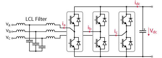
The Active Front End (AFE) is a family of controllable rectifiers that serve as AC to DC converters. Compared with the traditional diode rectifiers, the Active Front End allows for bidirectional power flow (i.e., regenerative power injection to the grid) and also actively shapes the current waveform to achieve low total harmonic distortion (THD) and high power factor. In practice, the Active Front End is usually used together with an LCL filter for further harmonic attenuation.
Given its bidirectional nature, the Active Front End is widely used in modern power systems as an interface between the AC grid and other converters, in applications such as variable-speed drives or fast electric vehicle chargers.
While this page considers a three-phase implementation of Active Front Ends, single-phase equivalents are also implementable, such as the totem-pole PFC rectifier. It is often part of single-phase onboard battery chargers in EVs.
DC bus pre-charging of the Active Front End
As discussed in DC bus pre-charging techniques, the grid-connected operation of power converters requires its DC bus voltage to be higher than the rectified AC voltage at all times (\(V_{dc} \ge V_{LL, peak}\)) to avoid uncontrolled currents to flow from the grid to the converter through its anti-parallel diodes. In particular, when first connecting an Active Front End to the grid, a proper DC bus precharge mechanism is required to avoid potentially destructive inrush currents.
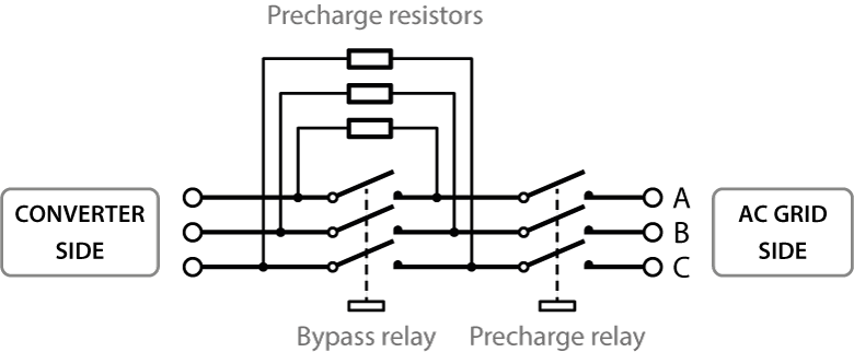
When using imperix power modules to implement an Active Front End, the Grid Connection Panel can be used as a current-limiting circuit during precharge. The precharge and bypass relays have to be actuated from the user code of the B-Box controller using, e.g., a state-machine logic as provided in DC bus pre-charging techniques.
Alternatively, when using the TPI8032 to implement an Active Front End, a precharge and protection circuit is already built-in, and the RLY block automatically handles the safe connection to the grid with an FPGA-based protection module. The protection module also protects the device by opening all the relays when the DC voltage drops below the rectified AC voltage, or when the system enters the fault state. More information can be found on the device datasheet.
Particular considerations when using the TPI8032
This section introduces considerations specifically related to the TPI 8032. It is strongly recommended to read them first before connecting the TPI8032 to the AC grid.
– If the relays are closed with zero AC voltage, and then AC voltage is applied.
– If increasing the grid voltage when the relays are closed. This may happen when the grid is supplied by a variable autotransformer or a grid emulator.
To avoid this issue, it is recommended that AC voltage be applied before closing the relays and that the relays be opened before the grid voltage applied to the AC terminals is increased.
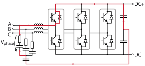
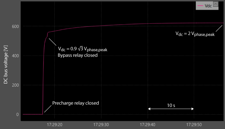
Given the specific filter configuration of the TPI8032 – with the neutral point of the filter capacitors connected to the DC bus midpoint – the DC bus naturally charges to a higher voltage than the typical rectified voltage \(V_{LL, peak}=\sqrt{3}V_{phase, peak}\) (560Vdc with 400Vac grid). With that topology, the DC bus can charge up to \(2V_{phase, peak}\) (650Vdc with 400Vac grid), through the current path illustrated below.
The working principle of the RLY driver is as follows:
- Upon connection request in the user code (input of the RLY driver set to 1), the precharge relay is closed, and the DC bus charges through the precharge resistors.
- When the DC voltage reaches \(V_{dc, min}=0.9\sqrt{3}V_{phase, peak}\), the bypass relay is automatically closed.
During the precharge procedure, the DC voltage therefore evolves as in the graph below:
Control of the Active Front End
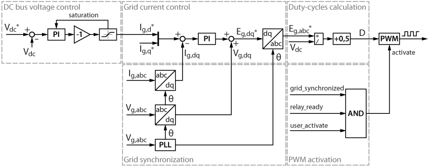
The control of an Active Front End consists, most of the time, of the control of the DC bus voltage to a given reference and the power factor to unity. This page focuses only on the DC voltage control, which can typically be achieved with a cascaded structure, with a grid current controller in the grid-synchronous reference frame as the inner loop and a DC voltage controller as the outer loop. In addition, some other functionalities are needed, such as synchronization with the AC grid and appropriate activation of the PWM output. Each of these elements is detailed hereafter and illustrated in the diagram below.
Grid synchronization
An accurate synchronization system is required to track the grid’s phase and frequency. This note uses an SRF PLL as an example, which is a simple and widely used solution for synchronization with the three-phase grid. Another possible technique is introduced in SOGI PLL, which has better dynamic performance and can work with a single-phase grid.
Grid current control
The grid currents are controlled by two PI controllers in the grid-synchronous (dq) reference frame using the same technique introduced in Grid-Following Inverter (GFLI). The control parameters \(K_{p,I}\) and \(K_{i,I}\) are tuned using the Magnitude Optimum (MO), with the plant parameters \(L_g\) and \(R_g\) available in the TPI 8032 datasheet.
$$\begin{aligned} K_{p,I} =\frac{L_g}{2T_d} \\ \\ K_{i,I} =\frac{R_g}{2T_d}\end{aligned}$$
| Lg | 950 µH |
| Rg | 54 mΩ |
The parameter \(T_d\) represents the sum of all the small delays in the system, such as the computation and modulation delays. The product note Time delay determination for closed-loop control explains how to determine the total delay of the system. Please also note that if synchronous averaging is enabled, which is the case by default in TPI ADC blocks, an additional delay of \(0.5T_s\) has to be considered.
DC bus voltage control
The design and tuning of the DC voltage controller are similar to those introduced in Cascaded H-bridge converter control. The controller controls the DC bus voltage by changing the d-axis current \(I_{g,d}\). The current reference \(I_{g,d}^{*}\) has to be multiplied by \(-1\) because the positive direction of the grid current is, by convention, from the converter to the grid. To avoid over-current, a saturation block is added after the PI controller output. When the output saturates, the integrator is clamped to avoid windup.
The control parameters \(K_{p,V}\) and \(K_{i,V}\) are tuned based on the bandwidth \( f_{BW} \) and phase margin \(\phi_{PM}\) of the system:
$$ K_{p,V} = 2\pi f_{BW}\cdot\frac{2}{3}\cdot \frac{V_{dc,eq}}{V_{g,d}} \cdot C_{dc,eq}\cdot \sqrt{\frac{\text{tan}^2(\phi_{PM})}{1+\text{tan}^2(\phi_{PM})}} $$
$$ K_{i,V} = K_{p,V}\cdot\frac{2\pi f_{BW}}{\text{tan}(\phi_{PM})} $$
By choosing the bandwidth as \( f_{BW} = 50 \, \text{Hz} \) and the phase margin as \( \phi_{PM} = 70° \), a good compromise between tracking dynamics and damping is obtained in simulation and experimentally.
The q-axis current \(I_{g,q}^{*}\) is controlled separately by a tunable parameter for possible power factor correction uses.
PWM activation
The provided model implements a simple logic that allows activation of the PWM outputs when:
- the PLL is synchronized with the grid,
- the relays are closed and ready to operate, and
- the tunable parameter
activateis set to ‘1’ by the user.
Control implementation with ACG SDK
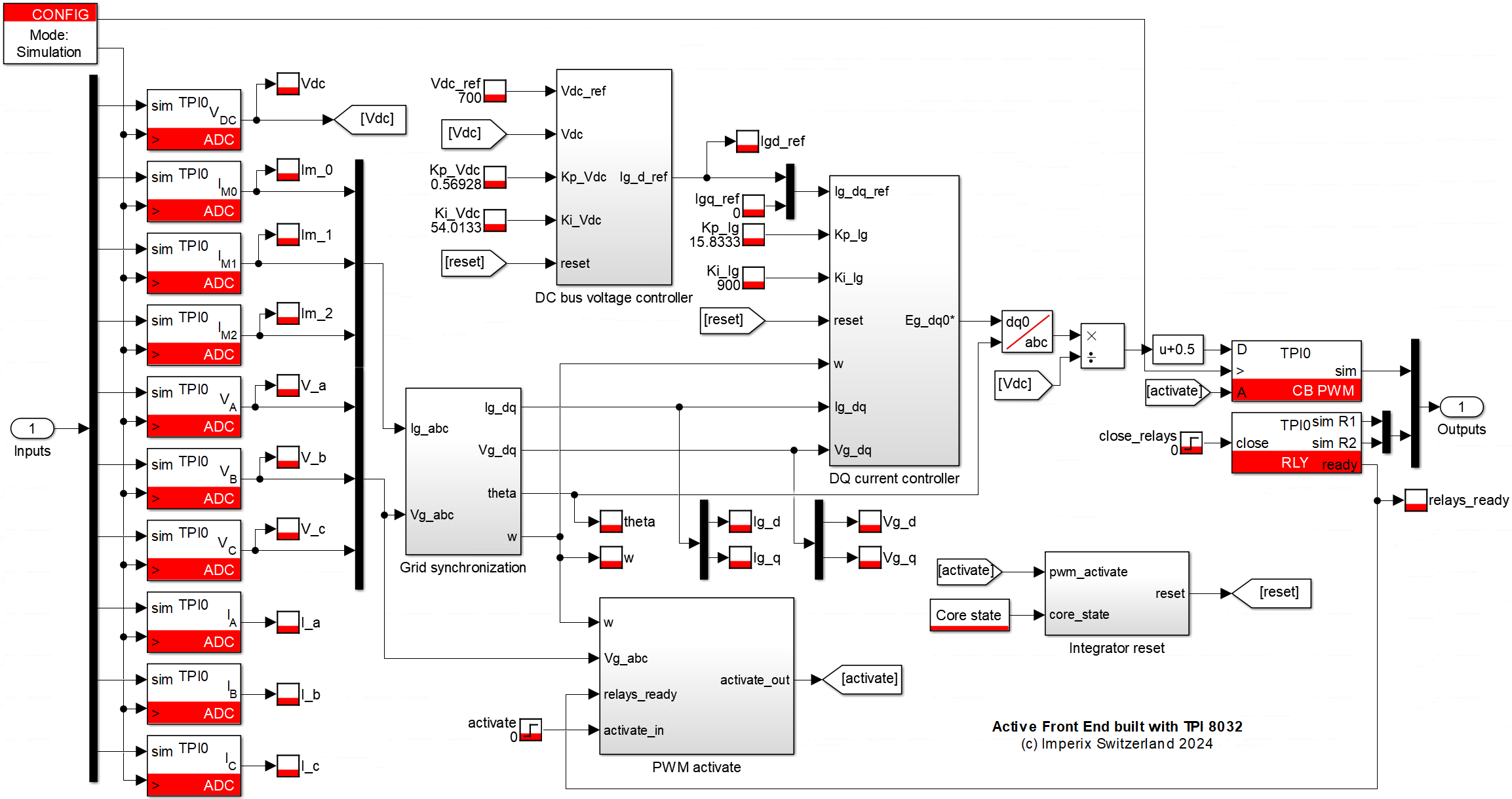
The described control algorithm of the Active Front End was implemented in Simulink and is available for download below.
The minimum requirements are:
- Imperix ACG SDK 2024.2 or newer, available here
- MATLAB Simulink R2016a or newer
- For simulation only: Simscape Electrical
Experimental results
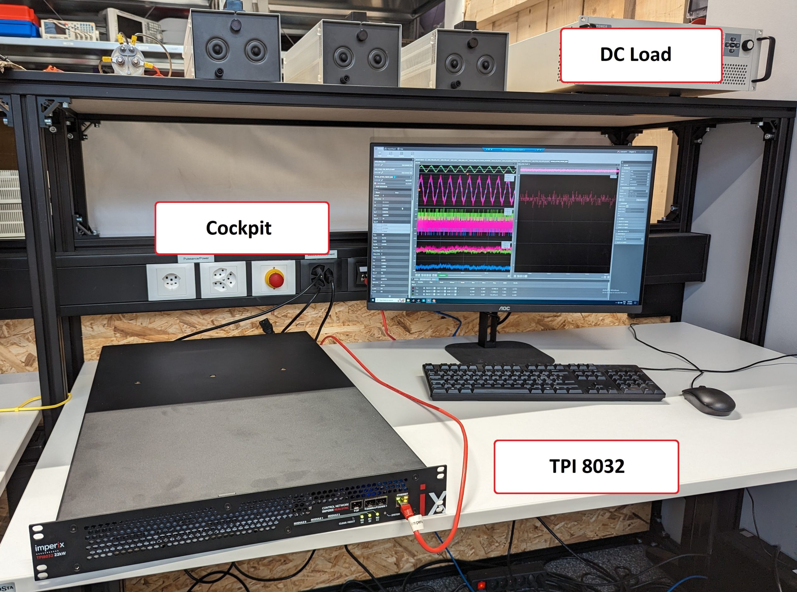
The example model was tested on an experimental testbench using a TPI 8032. A DC relay in series with a resistive load is connected on the DC side to perform changes on the DC load current. The wiring scheme and the experiment setup are shown below.
The operating conditions are:
| Control frequency [kHz] | 50 |
| RMS grid voltage (phase to neutral) [V] | 230 |
| DC bus voltage range [V] | 650 – 800 |
| Grid frequency [Hz] | 50 |
| DC load resistance [Ω] | 3 x 10⁶ |
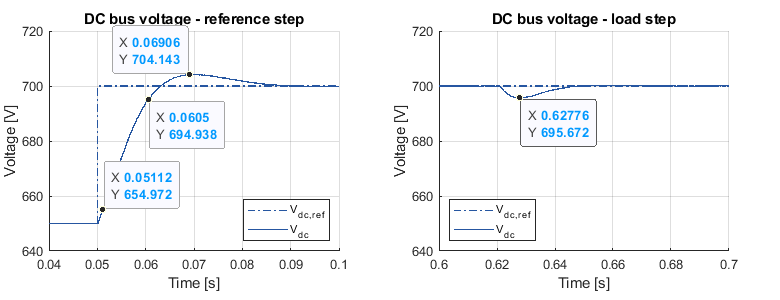
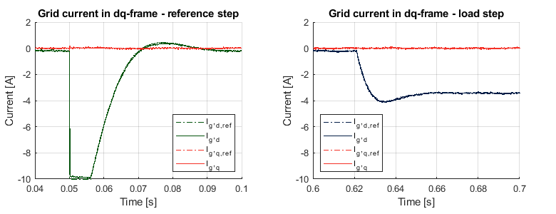
The following figures show the experimental results when a 50V step is performed on the DC bus voltage reference (left) and when a 318Ω load is connected to the DC bus (right). The left graph shows a 10% to 90% rise time of 9ms. In theory, for a one-stage low-pass RC network, for a bandwidth of 50Hz, the 10% to 90% rise time should be:
$$ t_r = \frac{0.35}{f_{BW}} = 7 \, \text{ms}$$
This approximately matches the experimental result. Overall, the voltage controller achieves a settling time of 50ms with less than 10% overshoot. Considering the 1.5mF capacitance on the DC bus, this performance is good.
The graph on the right shows around 4V voltage drop and 40ms recovery time when 2.2A DC load current is applied. To further improve the resistance against load changes, the DC load current can be fed forward to the controller, as introduced in [2].
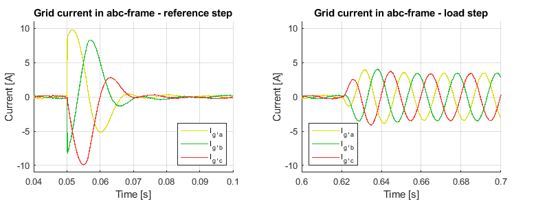
The grid current waveforms show the reference is rapidly tracked by the current controllers during the experiment.
To go further
… with the Active Front End
The following application examples show how the Active Front End can be used in more complicated applications.
- Back-to-back three-phase converter
- Fast electric vehicle charger
- Onboard battery charger for electric vehicles
… with the TPI 8032
The TPI 8032 can be easily programmed to fit any purpose. More examples of TPI in microgrid applications are available in the knowledge base, such as:
Academic reference
[1] Karl J. Åström and Tore Hägglund; “Advanced PID Control”; 1995
[2] Chandra Bajracharya; “Control of VSC-HVDC for wind power”; NTNU; 2008


