Table of Contents
This technical note presents an I-f startup method for an electric motor drive when controlled in a sensorless fashion using a back-EMF estimator. It specifically addresses Permanent Magnet Synchronous Machines (PMSM).
First, the note introduces the I-f startup method. Then, a possible transition technique to the sensorless Field-Oriented Control (FOC) motor control is presented.
Finally, a practical control implementation is introduced, targeting the B-Box RCP or B-Board PRO with the ACG SDK on Simulink. Please note that imperix offers a ready-to-use motor drive system to develop and test motor control techniques. More details can be found in the Motor Testbench quick start guide.
Software resources
Context
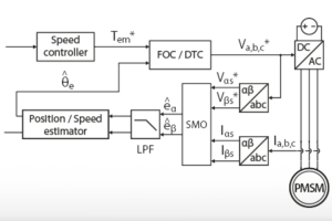
The SMO-based sensorless control technique presented in TN136, like any technique based on back-EMF estimation, has a major drawback: the amplitude of the back-EMF is proportional to the speed of the motor, which makes it difficult to estimate the back-EMF accurately at low speed. In particular, at standstill there is no back-EMF at all, making it challenging to start the motor in the first place.
This technical note presents a possible implementation of a startup strategy for a PMSM sensorless Field-Oriented Control, using open-loop I-f control.
Motor startup strategies
Several methods can be used to start up a PMSM-based electric drive without initial position information. This section briefly introduces 3 of these methods and justifies the choice of the I-f startup method for the present implementation.
High-frequency component injection
A first technique is to use a high-frequency component injection method, as described in [1]. This is a sensorless technique that produces an accurate speed estimation on the whole speed range of the machine. However, it relies on the anisotropy of the rotor which makes it unsuitable for the isotropic PMSM used in the TN136.
In reality, a PMSM is never truly isotropic. At the junction between two magnets, the magnetic flux tends to pass directly from one magnet to the other, rather than passing through the stator windings [2]. Therefore, the flux near the junction does not contribute to the torque generation. As a result, the rotor is always anisotropic, even if the magnets are surface mounted.
Theoretically, this would allow using the high-frequency component injection method with an SPMSM. However, it is not trivial in practice to exploit this small anisotropy.
V/f motor control
Unlike the high-frequency component injection method, the V/f control [3] is not dependent on the anisotropy of the machine. What’s more, it is also much simpler to implement.
Unfortunately, the V/f control is a scalar method, which doesn’t rely on a Rotating Reference Frame, unlike FOC. Therefore, the transition from V/f startup to FOC operation requires special consideration, in order to align the stator flux in the RRF and ensure a smooth transition, which defeats the simplicity of the V/f control.
I-f startup
The aforementioned problem of the stator flux orientation is addressed by the I-f starting method [4][5][6]. The I-f method draws its inspiration from the V/f startup: both methods receive a speed reference ramp as an input and generate a voltage reference for the drive converter. Since there is no speed feedback at this point, the startup is in open-loop. However, assuming for now that these methods are stable, the actual speed of the machine will follow the acceleration from the reference even if there is a tracking error in open-loop.
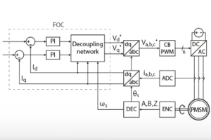
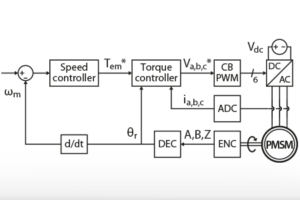
The main difference between the two methods is that the I-f startup method uses the current controller from a Field-Oriented Control to accelerate the machine at constant torque. This way, the transition to the sensorless FOC is easier than with the V/f control since both the I-f startup and the FOC use the same current controller (see figure below): the I-f method “understands” the concept of dq axes. What’s more, the I-f startup method is better suited under load because it has a torque regulation, unlike V/f control.
Since this technical note is covering the startup phase of a sensorless FOC of an isotropic PMSM, the I-f method is the best option of the 3 methods introduced above.
")
I-f PMSM startup method
This section describes the working principles of an I-f startup method. The procedure is divided into two phases:
- Phase I: the machine is accelerated in an open-loop manner
- Phase II: when particular conditions are met, the control switches smoothly to sensorless FOC
Phase I: acceleration
In a first phase, the goal of the I-f startup method is to accelerate the PMSM until the speed estimation from the SMO is “accurate enough”. For this technical note, “accurate enough” means that the speed control with the sensorless FOC is at least stable. As a rule of thumb, the minimum operating speed should be in the 10-20% range of the nominal speed, according to [4], [5], [6] and as validated experimentally. The acceleration of the motor is then set by the difference between the electro-mechanical torque \(T_{em}\) and the load torque \(T_L\), as explained in TN114:
$$(1) \qquad \frac{d \omega _m}{dt} = \frac{T_{em} – T_L}{J_m} = \frac{\cfrac{3}{2} p \Psi_{PM}I_{qs} – T_L}{J_m}$$
According to (1), the PMSM could be accelerated by simply applying a constant electro-mechanical torque. However, the FOC requires the position of the rotor which is not accurate at low speed. Instead, the I-f method uses a virtual reference rotating frame [4]. The position of the virtual frame is defined by integrating the frequency ramp and the ramp acts as a speed reference, even if no speed controller is involved.
$$(2) \qquad \left\{ \begin{array}{rl} \omega _m^* &= \cfrac{d\omega _m^*}{dt} \times t \\ \displaystyle \theta _e^* &= \int_{t_0}^{t} \omega _e^* \space dt = p \int_{t_0}^{t} \omega _m^* \space dt \end{array}\right.$$
\(\omega_m^*\) is the reference mechanical speed, \(p\) the number of pole pairs, \(\omega_e^*\) the reference electrical speed, and \(\theta_e^*\) the reference electrical angle of the rotor.
Since there is no feedback of the rotor position, the virtual and real frames may be misaligned. The alignment error is \(\theta _{err}=\theta_e-\theta_e^*\) and its variation depends on the speed difference between both frames:
$$(3) \qquad \frac{d\theta _{err}}{dt} = \omega _e – \omega _e^*$$
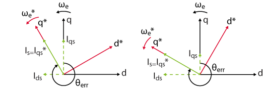
During this acceleration phase, the current controller of the FOC aligns the current space vector on the q-axis of the virtual rotating frame. However, due to the angle error, the current in the real rotating frame may have a non-zero component on the d-axis. What’s more, two values of \(\theta_{err}\) lead to the same \(I_{qs}\) component, depending on if the virtual rotating frame is leading or lagging, compared to the real rotating frame (see below). Both cases lead to different behaviors, as developed in the following two sections.
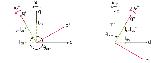
leading the real rotating frame (left) or lagging (right)
Leading virtual RRF
Let us consider first the case when the virtual RRF is leading the real RRF. Intuitively, the system cannot be stable because the real current \(I_{qs}\) is smaller than the reference \(I_{qs}^*\), due to the angle error \(\theta _{err}\). Therefore, the real torque applied to the rotor is too low to accelerate the real RRF as fast as the virtual RRF. As a result, the virtual rotating frame will be leading even more and the real current on the q-axis will become even smaller as illustrated below. When the virtual frame is leading by more than \(\pi/2\), the machine will stall.
the real torque is reduced instead of being increased.
Lagging virtual RRF
Let us consider now the case when the virtual RRF is lagging behind the real RRF. If \(I_{qs}^* = \text{cst}\) is large enough, the high torque will accelerate the machine faster than the variation of the speed reference. In this case, \(\omega _e > \omega _e^*\) and according to (3) the error angle increases. Since \(I_{qs}^*\) is lagging behind \(I_s\), \(I_{qs} < I_{qs}^*\) and the machine decelerates. When \(\theta _{err} > \pi / 2\), the effective torque becomes negative, even if the reference torque is positive. As a result, the rotor decelerates abruptly and the virtual rotating frame catches up with the real rotating frame. Once again, the large torque re-accelerates the machine, and the virtual frame is always lagging behind. In the end, the real torque is oscillating around the reference torque but the control is stable. This phenomenon is called the self-stabilization mechanism in [6].
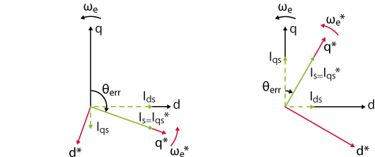
negative the rotor decelerates in a stable situation (right).
In summary, the I-f control is stable if – for a given reference acceleration – the torque reference is high enough to ensure that the virtual rotating frame is always lagging behind the real rotating frame.
Mathematically speaking, the equation (1) can be modified to express the stability condition:
$$(4) \qquad \frac{d \omega _m^*}{dt} < \cfrac{\cfrac{3}{2} p \Psi_{PM}I_{qs}^* – T_{L,max}}{J_m}$$
where \(T_{L,max}\) is the maximal load torque expected at startup. According to this condition, the current reference should be set as high as possible to ensure the stability of the startup. Therefore, the current reference could be chosen as the nominal current of the PMSM because this is the largest possible current that will not damage the machine in steady-state. However, be aware that a large step in the current reference results in a large inrush current.
Phase II: transition to sensorless FOC
Challenges
In a second phase, the I-f control should hand over the reins to the sensorless FOC. However, as mentioned previously, there is a misalignment of the stator current vector due to the angle error between the real and virtual rotating frames.
The figure below illustrates the problem: on the left, the current vector is aligned on the q*-axis by the current controller but, in the real RRF, the current has a non-zero d-axis component. If in this situation, the control is switched to the sensorless FOC, the latter will abruptly align the current vector on the real q-axis current (see illustration on the right). What’s more, the amplitude of the current reference \(I_{qs}^*\) will also be suddenly changed by the speed controller. Mechanically speaking, these two changes translate into a jolt due to the sudden torque variation. Depending on the amplitude of this jolt, the control bandwidth of the speed controller may not be large enough to ensure the stability of the system.
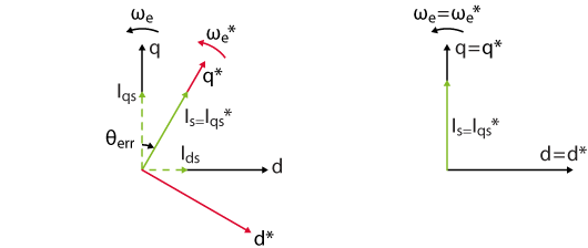
(right) rotational frame and current reference from the sensorless FOC
Even if the speed controller is able to ensure the stability of the system, a jolt on the rotor may be undesirable for some applications. For example, when an escalator driven by a PMSM is started, it should not make a jolt. Therefore, there is a need for a smooth transition between the I-f startup phase and the sensorless FOC.
Constant speed transition
A transition technique at constant speed is proposed in [4]. The principle is the following: during a stable I-f startup, the virtual RRF is lagging behind the real one. Therefore, the real RRF should be slowly decelerated until the virtual q*-axis is aligned with the real q-axis. This way, the stator current vector is already aligned on the q-axis when switching to the FOC.
Here is how the virtual RRF can be aligned on the real one [4]:
- The speed reference is maintained at a constant value. It should be “high enough” to ensure the proper operation of the sensorless FOC.
- According to equation (1), the real RRF can be slowed down by decreasing \(I_{qs}^*\). As a result, the angle error \(\theta_{err}\) will also decrease.
- If \(\theta_{err} < \epsilon_{\theta}\), where \(\epsilon _{\theta}\) is the desired tolerance, the control is handed over to the sensorless FOC. At that moment, the current reference \(I_{qs}^*\) is almost aligned on the q-axis of the real rotating frame, as in the case of the sensorless FOC. Therefore, it is reasonable to expect that \(I_{qs}^*\) is close to the value desired by the speed controller.
The simulation results below illustrate the gradual alignment of the virtual RRF with the real one when the current reference \(I_{qs}^*\) is gradually reduced.
Additional comments
This section addresses a few additional implementation details that were set up to obtain the experimental results presented at the end of this page.
The first one relates to the estimation of the angle error \(\theta _{err}\). Since the real rotor angle is not available in practice, the only available value is its estimation:
$$(5) \qquad \hat \theta _{err} = \hat \theta _e – \theta _e^* = (\theta _e + \Delta \hat \theta) – \theta _e^* = \theta _{err} + \Delta \hat \theta$$
which is affected by \(\Delta \hat \theta\), the estimation error of the rotor position observer. Due to this estimation error, the stability criterion \(\theta _{err} > 0\) is not ensured at the moment of the transition (i.e. when \(\hat\theta_{err} = \epsilon_{\theta}\)). Therefore, mathematically, the tolerance \(\epsilon _{\theta}\) should be larger than \(\Delta \hat \theta\). In practice, \(\epsilon _{\theta}\) should be large enough to ensure that the startup is stable at the moment of transition to sensorless control.
Another consequence is that the transition condition \(\hat\theta_{err} < \epsilon_{\theta}\) may be hard to reach for a large estimation error \(\Delta \hat \theta\). In this case, the decreasing current reference \(I_{qs}^*\) may become negative before \(\hat\theta_{err} < \epsilon_{\theta}\) is met. This can be the case under light load conditions, where low stator currents lead to a high estimation error \(\Delta \hat \theta\). The light load also means that a negative \(I_{qs}^*\) would cause the machine to accelerate in the opposite direction. To avoid that behavior, an additional transition condition can be added: if \(I_{qs}^*\) is smaller than a threshold \(\epsilon _I\), the control switches to the sensorless FOC.
Finally, it is important that the integral term of the speed controller is initialized in a suitable way. If the integral term is zero at the moment of transition, the current reference will drop abruptly. If the transition occurs at \(t_1\), a reasonable initial value is the torque produced by \(I_{qs}^*(t_1)\). In [4], the authors propose a theoretical way to estimate \(I_{qs}^*(t_1)\). Alternatively, the initial value can be derived from \(I_{qs}^*(t_1-T_s)\), the current reference that was computed by the I-f method just before the transition. The initial value of the integral term is therefore \(\frac{3}{2}p \Psi_{pm}I_{qs}^*(t_1-T_s)\).
Summary of the I-f startup method
The whole I-f startup method can be summarized in the following steps:
- Set the references to \(I_{qs}^* = \text{cst}\) and \(\omega _m^* = \frac{d\omega _m^*}{dt} \times t\). Make sure to fulfill the stability condition (4).
- Once \(\omega_m^* \geq \omega_{m,min}\), keep the speed reference constant. Let us call this moment \(t_0\).
- Reduce the current reference: \(I_{qs}^*(t) = I_{qs}^*(t_0) – \frac{d I_{qs}^*}{dt} (t – t_0)\)
- Switch to the sensorless FOC if \(\hat \theta_{err} < \epsilon_{\theta}\) or \(I_{qs}^* < \epsilon _{I}\).
- At that stage, experimental tests showed that it was necessary to keep the speed reference constant for 1-2 seconds before starting to track the desired speed (see experimental section).
")
I-f startup method implementation on a B-Box controller
The file provided in the Download section contains a complete implementation of a SMO-based sensorless speed control of a PMSM with I-f startup. The implementation uses the ACG SDK on Simulink.
Virtual reference frame
The position of the virtual frame is obtained simply by integrating the speed reference, as shown below:
")
Selection of the sensorless method
The figure below shows how the control selects the speed/position from either the I-f or the SMO-based methods. The “sensorless_ready” signal is given by the operation state machine, once the minimal speed has been reached.
")
Torque reference
The torque reference comes either directly from the I-f control or from the speed controller. The integrator in the speed controller is initialized by taking the last value of the q-axis current reference from the I-f control.
")
Tuning of the speed controller
The tuning of the cascaded control for the same PMSM is already detailed in the technical notes TN111 for the inner-loop and TN114 for the outer-loop. See the Experimental results section for the machine parameters.
For this particular implementation of a sensorless FOC, the estimated speed fed to the speed controller is always lagging behind the real speed due to multiple low-pass filters. There is a 2nd order LPF with a 60 Hz cut-off frequency after the SMO and a 1st order LPF with a 10 Hz cut-off frequency just before the speed controller (see above). The purpose of this last LPF is to filter the speed estimation noise. As a result, the dynamic of the speed controller must be adapted to take the estimation delay into account.
The effect of the low-pass filters is taken into account by the sensing delay because even if the speed is estimated it is inferred from current measurements.
$$(6) \qquad \left\{ \begin{array} \displaystyle T_{sens} = \cfrac{2}{2 \pi \times 60 \,\text{Hz}} + \cfrac{1}{2\pi \times 10\,\text{Hz}} = 21.2 \,\text{ms} \\[5pt] \displaystyle T_{ctrl} = N \times T_s = \cfrac{100}{20 \, \text{kHz}} = 5 \,\text{ms}\\[5pt] \displaystyle T_{PWM} = \cfrac{T_{sw}}{2} = \cfrac{1}{2 \times 20 \, \text{kHz}} = 25 \,\text{µs} \end{array}\right.$$
The total delay of the outer-loop is then the sum of the small time constants:
$$(7) \qquad T_{tot} = T_{sens} + T_{ctrl} + T_{PWM} = 26.225 \,\text{ms}$$
The measurement delay is predominant in the dynamic of the speed control and cannot be neglected. Using the symmetrical optimum criterion and taking the measurement delay into account the parameters of the PIs are computed as:
$$(8) \qquad \left\{ \begin{array}{rl} \displaystyle T_n &= 4 \space T_{tot} = 104.9 \,\text{ms}\\[5pt] \displaystyle T_i &= 8 \space \cfrac{T_{tot}^2}{T_2} = 18.97 \,(\text{N}\,\text{m})^{-1} \\[5pt] \displaystyle K_p &= T_n \space / \space T_i = 0.006 \, \text{N}\,\text{m}\,\text{s}\\[5pt] \displaystyle K_i &= 1 \space / \space T_i = 0.053 \,\text{N}\,\text{m} \end{array}\right.$$
The table below summarizes the difference in tuning between the sensored and sensorless speed control.
| Sensored speed control | Sensorless speed control | |
|---|---|---|
| Total delay \(T_{tot}\) | 5.025 ms | 26.225 ms |
| Proportional gain \(K_p\) | 0.029 Nm s | 0.006 Nm s |
| Integral gain \(K_i\) | 1.43 Nm | 0.053 Nm |
Finite state machine
The figure below shows the finite state machine that handles the I-f startup and the transition to the sensorless FOC. Notice the presence of a “stabilization” state after the constant speed compensation: when the control switches to the sensorless FOC, the jump to the new rotating reference frame and to the speed controller introduces a transient oscillation of the speed. If the speed reference is changed during that transient, the control may crash, depending on the variation rate of the reference and the load conditions. A simple solution is to keep the speed reference constant for – say – 1 second to let the speed controller stabilize the machine.
")
Experimental results of the I-f startup method
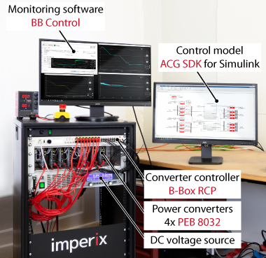
The experimental setup consists of a PMSM supplied by a voltage source inverter controlled by a B-Box prototyping controller. The FOC control is implemented using the graphical programming of ACG SDK library for Simulink. The power converter is built from 4x PEB 8032 phase-leg modules (3 phases and 1 braking chopper leg). Another PMSM connected to 3 power resistors is used as a brake to generate a load torque.
")
Machine parameters
The sensorless control was validated on a Permanent Magnets Synchronous Machine (PMSM) with the following parameters:
Model: Control techniques 095U2B300BACAA100190
| Parameter | Value | Unit |
| Rated power | 1.23 | kW |
| Pole pairs | 3 | – |
| Rated phase voltage | 460 | V |
| Rated phase current | 2.7 | A |
| Rated mechanical speed | 314 | rad/s |
| Rated torque | 3.9 | Nm |
| Stator resistance | 3.4 | Ohm |
| Stator inductance (d and q axis) | 12.15 | mH |
| Permanent magnet flux | 0.25 | Wb |
| Moment of inertia (PMSM only) | 2.9 | kg cm2 |
Test conditions
- Load torque: identical PMSM with 500 Ω resistive load on each phase
- DC link voltage: 600 V
- Inverter: 4x PEB8032 (one leg for braking chopper)
- Interrupt and sampling frequency: 20 kHz
- Sampling phase: 0.5
- PWM outputs: carrier-based
Results of I-f startup method
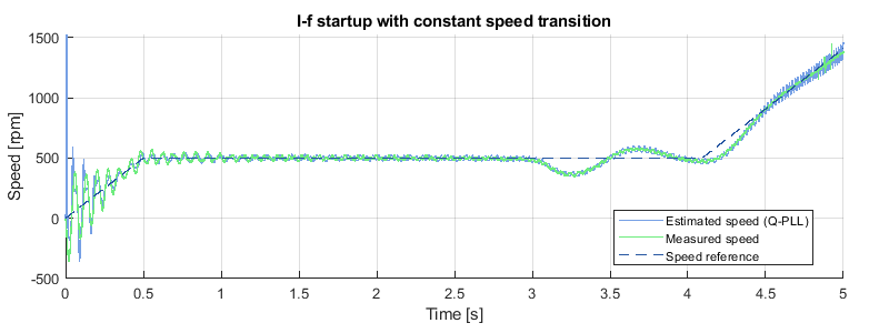
The speed reference was set to 3000 rpm with a constant speed transition at 500 rpm and a maximum rate of 1000 rpm/s. The oscillations of the measured speed around the reference at startup illustrate the self-stabilizing effect of the I-f method. When the PMSM has reached 500 rpm, the estimated speed is accurate, even if it was completely off at \(t = 0 \,\text{s}\). The transition to the sensorless FOC occurs at \(t = 3.1 \,\text{s}\). At that stage, the FSM keeps the speed reference constant during 1s to let the control compensate the jump to the FOC.
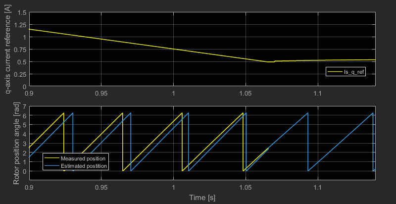
The next figure illustrates how the reduction of the current reference on the q-axis decreases the angle error between the virtual and real rotating frames. The exit conditions of the constant speed transition depend on the tolerances set for \(I_{qs}^*\) and \(\theta _e\): in this case \(\epsilon _I = 0.1 \,\text{A}\) and \(\epsilon _{\theta} = 0.1 \,\text{rad}\). As expected under load, the condition \(\theta_e < \epsilon_{\theta}\) is met first.
Note that the tests were carried out with \(I_{qs}^*\) equal to only 80% of the nominal current at startup to limit the in-rush current.
")
During the I-f startup, the current controller follows the d and q axes references inside the virtual rotating frame. Before alignement of the virtual rotating frame, the angle error was almost 90° as seen below (i.e. d and q axis almost inverted). In our tests, an encoder was used to compute the real dq currents.
")
Academic References
[1] A. Consoli, G. Scarcella and A. Testa, “Industry application of zero-speed sensorless control techniques for PM synchronous motors,” in IEEE Transactions on Industry Applications, vol. 37, no. 2, pp. 513-521, March-April 2001, doi: 10.1109/28.913716.
[2] D. Hanselman, “Brushless Permanent Magnet Motor Design”, 2nd edition, Magna Physics Publishing, USA, 2006, ISBN: 1-881855-15-5
[3] C. Aijun and J. Xinhai, “A stable V/F control method for permanent magnet synchronous motor drives,” 2017 IEEE Transportation Electrification Conference and Expo, Asia-Pacific (ITEC Asia-Pacific), Harbin, 2017, pp. 1-5, doi: 10.1109/ITEC-AP.2017.8080913.
[4] Z. Wang, K. Lu and F. Blaabjerg, “A Simple Startup Strategy Based on Current Regulation for Back-EMF-Based Sensorless Control of PMSM,” in IEEE Transactions on Power Electronics, vol. 27, no. 8, pp. 3817-3825, Aug. 2012, doi: 10.1109/TPEL.2012.2186464.
[5] J. Xing, Z. Qin, C. Lin and X. Jiang, “Research on Startup Process for Sensorless Control of PMSMs Based on I-F Method Combined With an Adaptive Compensator,” in IEEE Access, vol. 8, pp. 70812-70821, 2020, doi: 10.1109/ACCESS.2020.2987343.
[6] L. Wang, Y. Zhang, L. Zhao and G. Chen, “An Improved 3-Step Startup Method Based on Sensorless Vector Control of PMSM,” 2019 IEEE PES Asia-Pacific Power and Energy Engineering Conference (APPEEC), Macao, Macao, 2019, pp. 1-5, doi: 10.1109/APPEEC45492.2019.8994460.