Table of Contents
This application note is a complete example of how Direct Torque Control (DTC) can be implemented to control effectively the speed of a Permanent Magnet Synchronous Motor (PMSM). It gathers the content of different specialized technical notes and provides experimental results of the developed control.
In this note, the Direct Torque Control algorithm is developed using the imperix ACG SDK and is executed entirely on the CPU of a B-Box RCP controller.
Another approach is presented in FPGA-based DTC using Vivado HLS, where the Direct Torque Control algorithm is offloaded to the FPGA, showing much better control performance.
Please note that imperix offers a ready-to-use motor drive system to develop and test motor control techniques.
Downloads
The following zip file contains an example of control using MATLAB Simulink.
Minimum requirements.
- Imperix ACG SDK 3.5.1.1 or newer.
- MATLAB Simulink R2016a or newer.
- Plexim PLECS VIEWER 4.4.2 or newer (free)
General description and related notes
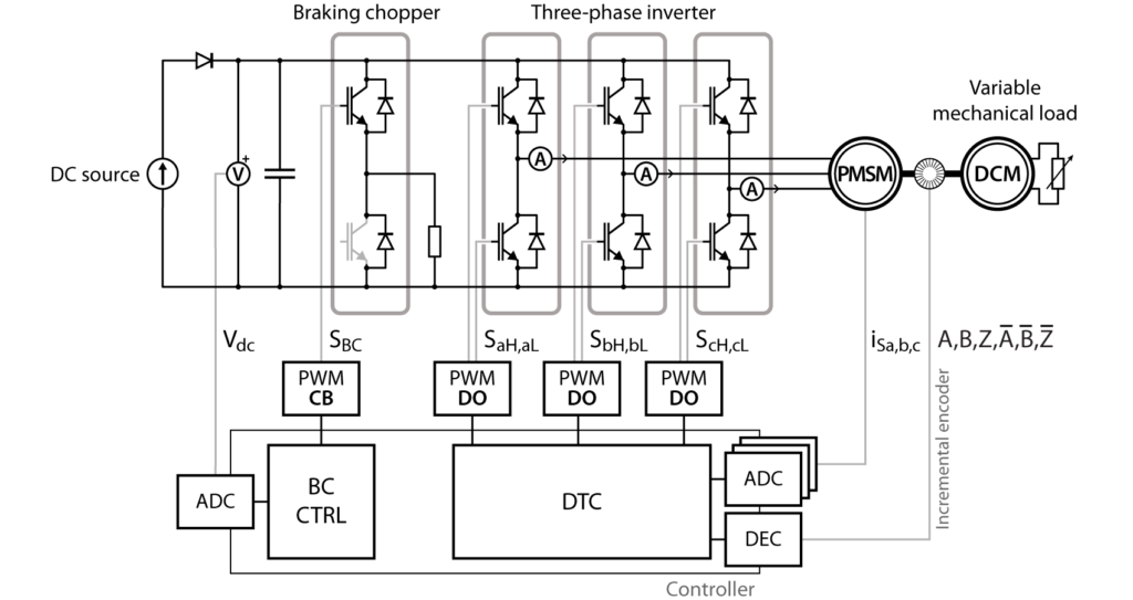
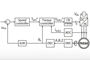
The overall system is depicted below and consists of a DC voltage source inverter supplying a PMSM. It notably comprises the following elements:
| Hardware | Software |
|---|---|
| Three-phase inverter Permanent magnet synchronous motor Braking chopper | Direct Torque Control Motor speed control (TN114) Position incremental decoder (PN104) Field weakening |
Setup presentation video
Direct Torque Control implementation
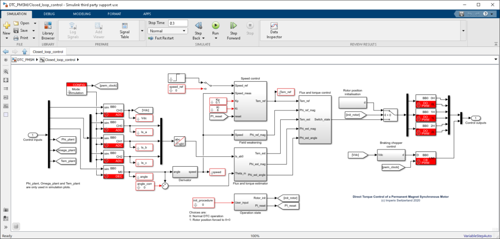
The different parts of the Direct Torque Control algorithm used in this note are presented in what follows.
In this example, the whole Direct Torque Control algorithm is run at the same rate as the sampling. Another approach would be to implement the elements that require a fast reaction time in FPGA (i.e. torque and flux estimator, hysteresis comparators, and the lookup tables). This approach is presented in the TN133.
Motor torque and flux estimator
The implemented torque and flux estimator is depicted below and is derived from [1]. It is based on the current model of the machine, where the estimated stator flux vector is derived from the stator currents (in the stationary reference frame) as well as the rotor position. This approach assumes that the stator inductance is independent of the rotor position and is thus only applicable to PMSMs with surface magnets.
This estimator has been chosen for its simplicity and accuracy, which mainly depends on rotor position measurement.

Speed control and motor torque reference
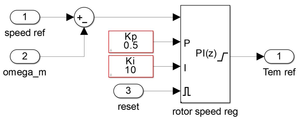
It is well known that a motor speed can be controlled by the applied torque. The plant can be modeled as a first-order transfer function, which can be effectively controlled by a simple PI controller.
The speed error is computed from the variation of the measured rotor position, as addressed in PN104. The output of the speed controller serves as torque reference for the Direct Torque Control algorithm and is limited to +/-110% of rated torque to avoid too high stator currents.
The speed control scheme is shown below, with tunable Kp and Ki coefficients. The reset input maintains the integral term of the PI controller equal to zero while speed control is not activated (i.e. while the B-Box PWM outputs are blocked and during the initialization of the rotor position).
Field weakening and flux reference
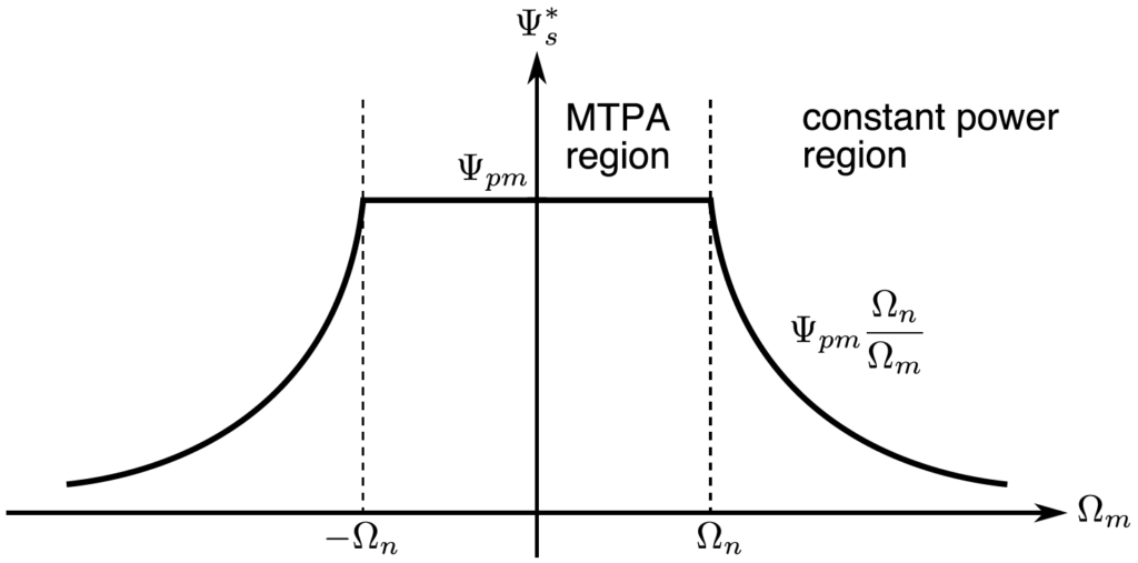
Beyond rated speed, the back-EMF must be reduced, in order to allow sufficient current flow in the motor while keeping the inverter output voltage within the motor rated voltage. In the present note, the back-EMF voltage is reduced by reducing the flux magnitude reference when the rotor speed exceeds the rated speed, as shown below. This is equivalent to imposing a negative current along the d-axis in Field Oriented Control.
Output PWM state and cycle delay
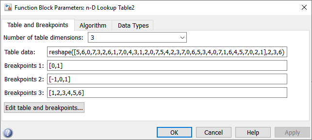
In Direct Torque Control, the torque, flux and sector states are directly converted into switching states with a lookup table, which makes its implementation particularly easy. The PWM signal generation process is shown below, with the detail of the output lookup table.
The switching state of each phase leg is then passed to a Direct Output PWM block (DO_PWM). Each of these blocks generates a complementary signal with a dead-time of 1 µs.
With DO_PWM, the inverter switching state is updated as soon as the interrupt computation is finished (plus a slight read delay [sub-μs]). The “reaction time” of the algorithm – i.e. the delay between a sampling instant and the application of the proper switching vector – is called the “cycle delay” and is the sum of the delays of the table below. This cycle delay, summed with the sampling period, defines the maximum overshoot of the controlled quantities.
| Delay | Value |
|---|---|
| ADC conversion | 2 μs |
| ADC read | ~400 ns |
| Interrupt duration | 5 μs |
| Driver write | ~400 ns |
| Total (cycle delay) | 8 μs |
Initialization of rotor position
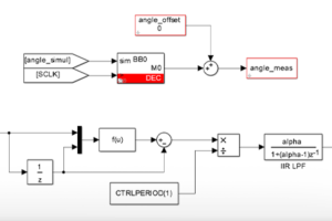
The rotor position encoder used in this application is an incremental encoder and needs therefore to be initialized in order to give an absolute position of the rotor. In the scope of this application example, the initialization phase is manual and has been simplified to the minimum viable solution; other approaches are of course possible. The initialization procedure is as follows:
- Before energizing the converter, one complete rotation of the rotor is done manually to reset the decoder counter with a pulse on the Z signal.
- The converter is energized (DC bus charged) and a current (typically 0.5 p.u.) is applied to the phase a of the motor. This will align the rotor with one of the poles of phase a.
- The offset of the measured angle is compensated, in order to measure 0 rad when the rotor is aligned with phase a (i.e. when the permanent magnet flux is completely along the α-axis).
This initialization is necessary for the flux estimator to work properly.
Braking chopper sizing and control
In drive applications, the braking energy of the controlled motor is sent back towards the DC side of the inverter. If the back-EMF voltage of the machine exceeds the DC bus voltage (which can occur at high speed or if reduced DC voltage is used), the generated energy is transferred toward the DC side through the inverter diodes. If the DC source is not capable of absorbing this energy (e.g. unidirectional source) this results in a rising DC bus voltage, possibly damaging the equipment. One possible way of avoiding such behavior is to add a braking chopper on the DC bus to burn the extra energy into a power resistor when needed.
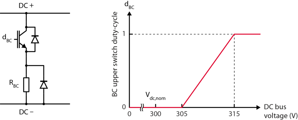
In the present implementation, the braking chopper is simply built with an additional phase leg and a braking resistor connected between its switching point and the DC- terminal of the converter. The lower switch is left open, and the duty-cycle applied on the upper switch allows to control the voltage on the resistor, and thus the amount of burnt power. The duty-cycle is:
$$d_{BC} = \cfrac{V_{dc}-V_{dc,n}-5}{10} = \cfrac{V_{dc}-305}{10},$$
which starts acting at 305 V and keeps the DC bus voltage below 315 V, as shown below.
The braking resistor was sized to allow sufficient power dissipation at 315 V. With a 50 Ω resistor, the braking chopper can dissipate up to 2 kW, which is well above the rated power of the machine.
Experimental implementation of Direct Torque Control
Quick-start guide
This section gives instructions on how to build and use a similar setup to drive a PMSM.
Required hardware
The converter part can be made with the following standard imperix equipment:
- 1x B-Box RCP controller with ACG SDK software
- 4x PEB8032 or PEB4046 half-bridge modules (very fast dV/dt can be harmful to some machines: IGBT modules may be preferred over SiC)
- 1x type C (or type A) rack for power modules
- 1x VHDCI breakout board for easy interfacing of the position encoder signals
- (optional) 1x emergency button connected to the interlock connector of the B-Box
I/Os configuration
A possible configuration is detailed below.
| Physical value | Sensor | B-Box input | Input configuration |
|---|---|---|---|
| \(I_{s,a}\) | PEB8032 | AI0 | Impedance: Low-Z | Gain: x8 | HW limits: [-3.5 V; +3.5 V] |
| \(I_{s,b}\) | PEB8032 | AI1 | Impedance: Low-Z | Gain: x8 | HW limits: [-3.5 V; +3.5 V] |
| \(I_{s,c}\) | PEB8032 | AI2 | Impedance: Low-Z | Gain: x8 | HW limits: [-3.5 V; +3.5 V] |
| \(V_{dc}\) | DIN800V * | AI3 | Impedance: High-Z | Gain: x8 | HW limits: [-1 V; 7 V] |
* can also be measured by the braking chopper leg embedded sensor
| PWM signal | B-Box PWM output |
|---|---|
| SaH – SaL | Channel 0 |
| SbH – SbL | Channel 1 |
| ScH – ScL | Channel 2 |
| SBC | Lane 6 (CH 3H) |
| GPI | Signal |
|---|---|
| 0 | A |
| 1 | B |
| 2 | Z |
| 3 | \A |
| 4 | \B |
| 5 | \Z |
Start-up procedure
The commissioning of the converter consists of the following steps:
- Configure the analog inputs of the B-Box, according to the table above.
- Build the Simulink model (Ctrl+B). This opens Cockpit and allows to connect to the B-Box. Further getting-started instructions are available in Programming and operating imperix controllers.
- Calibrate the current sensors by setting their offsets in their respective ADC blocks and re-build the model.
- Initialize the rotor position (see above section). To that end, in Cockpit, set
init_procedure = 1and enable/disable the PWM outputs (Ctrl+E/Ctrl+D). - Disable the PWM outputs and charge the DC bus (200 V) from the DC source.
- Set
init_procedure = 0, make sure thespeed_refhas a reasonable value and enable the PWM outputs.
Direct Torque Control test bench
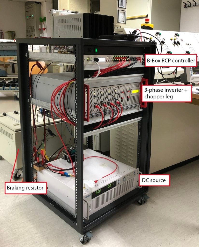
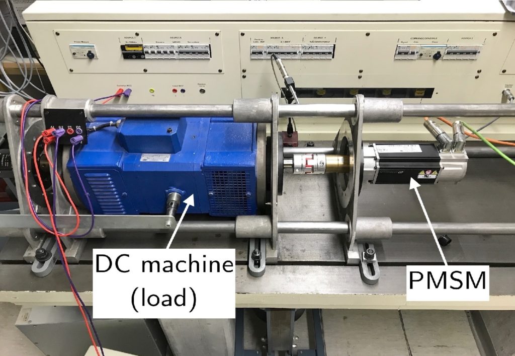
The Direct Torque Control algorithm has been validated experimentally using the following test bench. The different elements of the test bench are shown below.
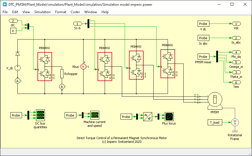
The inverter and the chopper leg are implemented with four PEB8032 modules. The machine parameters are:
| Model: Control techniques 095U2B300BACAA100190 | ||
|---|---|---|
| Parameter | Value | Unit |
| Rated power | 1.23 | kW |
| Pole pairs | 3 | – |
| Rated phase voltage | 460 | V |
| Rated phase current | 2.7 | A |
| Rated mechanical speed | 3000 | rpm |
| Rated torque | 3.9 | Nm |
| Stator resistance | 3.4 | Ohm |
| Stator inductance (d and q axis) | 24.3 | mH |
| Permanent magnet flux that encircles the stator winding | 0.25 | Wb |
| Moment of inertia (PMSM only) | 2.9 | kg cm2 |
The PMSM has a built-in encoder with differential outputs, Z signal and 4096 ppr.
The operating conditions are:
| Parameter | Value |
|---|---|
| Load torque | 2 Nm |
| DC link voltage | 200 V |
| Interrupt and sampling frequency (unless otherwise specified) | 40 kHz |
| Torque comparator tolerance | +/- 5% \(T_n\) = +/- 0.195 Nm |
| Flux comparator tolerance | +/- 2% \(\Psi_n\) = +/- 5 mWb |
Experimental results of Direct Torque Control
Flux and torque control
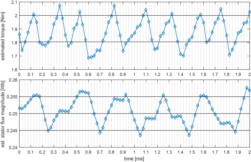
A detailed look at the samples of the torque and flux estimators is shown below. As soon as a comparator limit is reached, the appropriate switching vector is applied to produce the required effect on torque and flux. It can be seen that as soon as the torque estimation reaches the reference level (2 Nm), a zero switching vector is applied (000 or 111), with the effect of keeping the flux magnitude constant. It can also be noticed that the rate of decrease of torque is the fastest dynamic and can reach 4600 Nm/s. This suggests that the maximum limit violation of the estimated torque with a 40 kHz sampling is around 0.11 Nm.
Finally, it can be seen in the displayed window that the maximum switching frequency is 10 kHz. This maximum switching frequency is limited by a combination of the system dynamics (in particular motor inductance and DC bus voltage) and the hysteresis bandwidth of the comparators, but its absolute maximum value is half the control frequency.
Torque and flux ripples
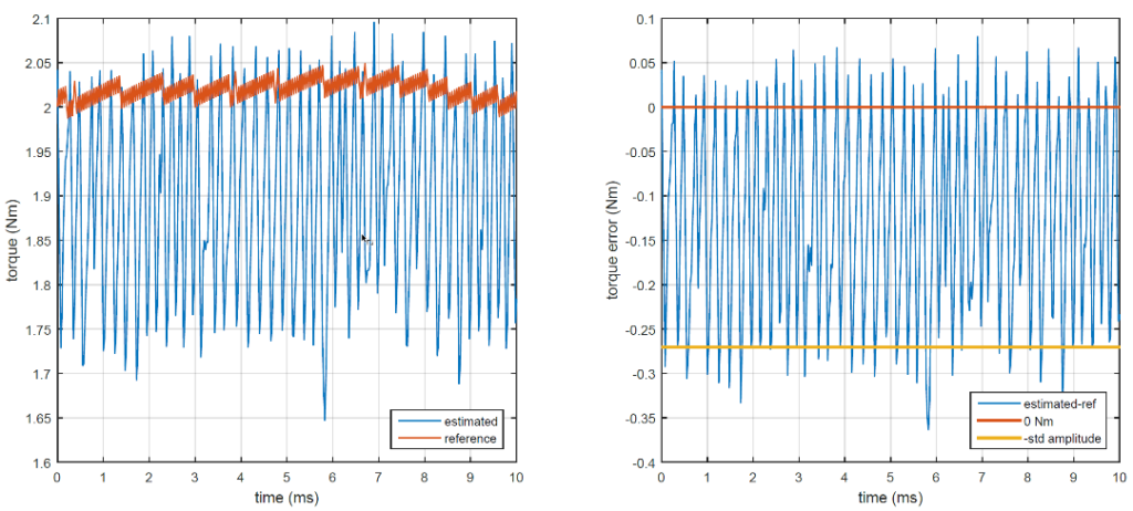
To characterize the ability of the control to keep the torque and flux values within their tolerance, the amplitude of their ripples has to be computed. It has been proposed in [2] to compute a “standard amplitude” of the ripples as follows:
$$A_{std} = \displaystyle\sqrt{\frac{3}{N}\sum^N_{i=1}(\hat{x}_i-x_i^*)^2},$$
with \(\hat{x}_i\) the ith sample of the estimated quantity, and \(x_i^*\) the ith sample of the reference value. This corresponds to the standard deviation around the reference value, multiplied by \(\sqrt{3}\) to get the amplitude of the ripples (amplitude of a triangular waveform). The figure below shows how the above-defined standard amplitude gives a fair idea of the mean amplitude of the torque ripples.
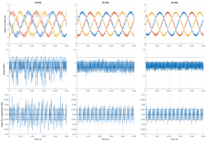
Using that definition, the following torque and flux ripples amplitudes have been obtained, for different sampling frequencies:
| Sampling and control frequency | Torque ripple standard amplitude | Flux ripple standard amplitude |
|---|---|---|
| [Nm] (%\(T_n\)) | [mWb] (%\(\Psi_n\)) | |
| 10 kHz | 0.58 (15%) | 13.26 (5.3%) |
| 20 kHz | 0.36 (9.3%) | 8.25 (3.3%) |
| 40 kHz | 0.27 (7.0%) | 6.74 (2.69%) |
| 150 kHz | 0.27 (7.0%) | 5.57 (2.23%) |
It is clear that increasing the sampling and control frequency decreases the torque and flux ripples, since the reaction time of the algorithm is shortened. The torque and flux ripples are inevitably larger than the hysteresis comparator thresholds, for the reasons already mentioned.
The same can be observed on the stator currents below. The operating speed is 100 rad/s and the load torque is 2 Nm. In that operating point, the torque is always an accelerating torque and is controlled between \(T_{em}^*\) and \(T_{em}^*-\varepsilon\).
Speed control
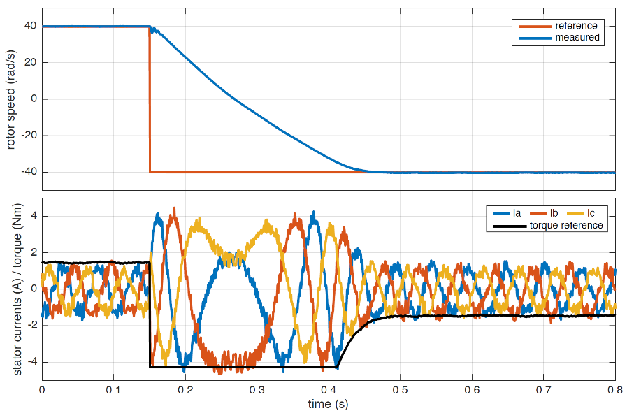
An example of a step change in the speed reference is shown below. It shows the ability of the control to follow a speed reversal from 40 to −40 rad/s. As the applied torque is a deceleration torque, the speed change is very fast and the complete speed reversal is achieved in just above 300 ms. The figure shows that the phase order is actually changed during the reversal.
Another interesting point to raise is the negative power flow when the speed and torque have opposite signs. In this case, the energy stored in the inertia of the rotating mass is transferred back towards the source and burned in the braking chopper.
Acknowledgment
The setup was built thanks to laboratory facilities made available by Prof. Samuel Chevailler at the HES-SO in Sion, Switzerland. Many thanks indeed!
References
[1] J. Mengjia, S. Cenwei, Q. Jianqi, and L. Ruiguang, “Stator flux estimation for direct torque
controlled surface mounted permanent magnet synchronous motor drives over wide speed region,” in 2005 International Conference on Electrical Machines and Systems, vol. 1, Sept 2005,
pp. 350–354.
[2] J. Orsinger, “Control of Variable-Speed Electric Drives“, Master’s thesis, Aug 2017


