Table of Contents
This technical note presents an FPGA-based Direct Torque Control (DTC) of a PMSM motor using Vivado HLS, coupled with the possibility to customize the FPGA firmware of a B-Box. This approach increases the responsiveness of the DTC implementation presented in AN004 by porting part of the control logic to the FPGA.
Xilinx Vivado High-Level Synthesis (HLS) is a tool that transforms C code into an RTL implementation that can be synthesized for an FPGA. The two main benefits are:
- It greatly facilitates the implementation of complex algorithms, as the designer can work at a higher level of abstraction (C/C++ code)
- It provides a higher system performance by offloading parts of the computations from the CPU to the FPGA and leverages the parallel architecture of the FPGA
Another example of high-level synthesis is presented in TN121, which addresses automated HDL code generation using Matlab HDL Coder.
Suggested prerequisites
- Information on how to set up the toolchain for the FPGA programming is available in the Vivado Design Suite installation page.
- Quick-start information on how to use the sandbox is provided in the getting started with FPGA page.
Software resources
Design choices
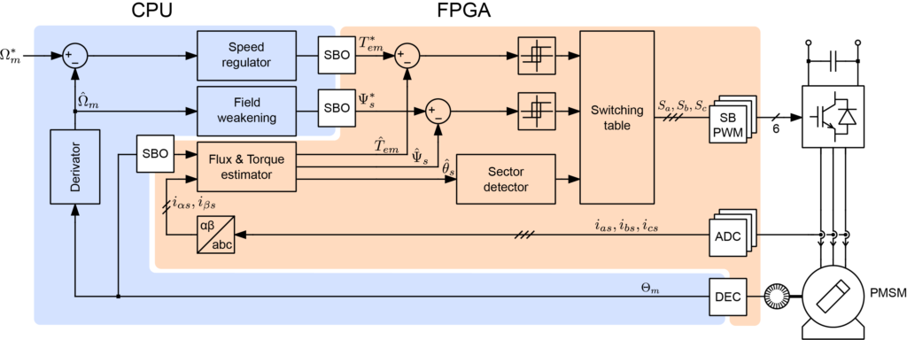
The DTC algorithm has been split into two parts:
- A fast part, implemented in the FPGA. This part requires a fast action to keep the torque and flux values within the hysteresis bounds. This corresponds to all the computations and logic resulting from the current measurements, which can be sampled at a high rate (typically 400 kHz).
- A slow part, implemented in the CPU and executed at the interrupt frequency (typically 40 kHz). This includes mainly the generation of the torque and flux references, which don’t require to be updated as fast as the sampling of the currents, given that the mechanical dynamics are much slower than the electrical ones.
The two parts are illustrated below:
HLS C code implementation
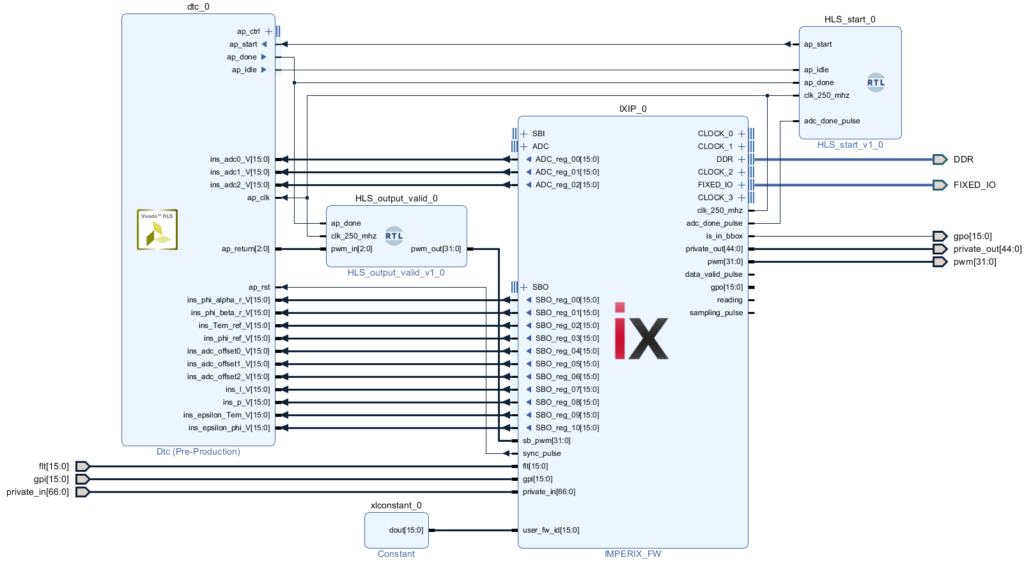
The logic ported to the FPGA is illustrated in the figure below. The ports are intended to be interfaced to the imperix firmware IP as follow:
adc_0,adc_1,adc_2: connected to theADCinterfacephi_alpha_r,phi_beta_r,Tem_ref,phi_ref: connected toSBOregisters (real-time registers)l,p,epsilon_Tem,epsilon_phi: connected toSBOregisters (configuration registers)pwm: connected tosb_pwm

The logic above has been translated into HLS C code. To derive an efficient hardware implementation, the following choices have been made:
- The inputs are 16-bit wide to be compatible with the
SBOandADCinterfaces of the imperix IP - The algorithm uses the ADC 16-bit results without applying any gain. This imposes to divide the setpoints coming from the CPU (Tem_ref, phi_ref, epsilon_Tem and epsilon_phi) by the gain that would have been applied to the ADC before sending them to the FPGA.
- The internal logic uses fixed-point arithmetic to be fast enough to handle the 250 MHz clock of the imperix IP and avoid the need to perform clock-domain crossing (CDC).
Ldranges between 0.001 and 0.1. To convey its value to the FPGA using a 16-bit integer, the original value is multiplied by 215 from the CPU and re-divided by the same amount in the HLS implementation.
HLS implementation source code:
Vivado HLS testbench
Vivado HLS provides a C/C++ simulator to validate designs. As illustrated in the figure below, a test bench has been developed to compare the PWM signals of the HLS fixed-point implementation against a floating-point model which is algorithmically equivalent to the Simulink implementation presented in AN004.
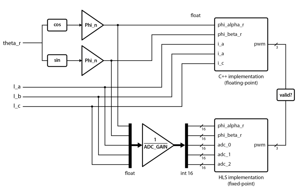
The test bench uses the following input signals:
- Three-phase currents
I_a,I_bandI_c: sinusoidal signals with a frequency of 1 kHz and an amplitude of 5 A. The signals are divided by ADC_GAIN to obtain 16-bit values representing the results of the ADCs. - Rotor flux angle
theta_r: a sawtooth with a frequency of 400 Hz and an amplitude of π.
The estimated torque will be sinusoidal, with a frequency of 1 kHz – 400 Hz = 600 Hz, as verified later.

The following values are set to the other inputs:
| input | C implementation | HLS implementation |
|---|---|---|
| Ld | 0.0243 | 0.0243 * 32768 |
| p | 3 | 3 |
| Tem_ref | 1 | 1 / ADC_GAIN |
| phi_ref | 0.3 | 0.3 / ADC_GAIN |
| epsilon_Tem | 0.095 | 0.095 / ADC_GAIN |
| epsilon_phi | 0.005 | 0.005 / ADC_GAIN |
Observing comparator inputs
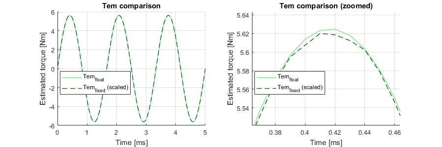
Various intermediate signals are extracted and saved in CSV files. This allows for the easy plotting of the simulation results for visual verification, which greatly helps during the design phase. The estimator outputs (torque, flux and flux angle) are shown below. The zoomed graphs show the approximation stemming from the use of fixed-point arithmetic. These small differences sometimes lead to a hysteresis state difference between the two implementations when a signal is close to a comparator limit.


Verifying PWM signals
Due to the approximation mentioned in the last section, we expect and tolerate that the PWM signals have a one-period difference. With this in mind, the following self-test mechanism has been implemented:
for (int i = 0; i < ITERATIONS; i++)
{

  // ... some code

  int pwm_float = dtc_float(tb_ins_float, tb_outs_float);

  // ... some code

  int pwm_dut = dtc(tb_ins,tb_outs);

  if((pwm_dut != pwm_float))
  {
    diffs++;
    printf("diff #%d at i = %d\n", diffs, i);

    // error if PWM are different for two iterations
    if(last_diff){
      errors++;
      printf("error #%d at i = %d\n", errors, i);
    }
    last_diff = 1;
  }
  else
  {
    last_diff = 0;
  }
}

if (errors > 0)
  printf("------ Test failed ------\n");
else
  printf("------ Test passed ------\n");

printf("Iterations: %d\n", ITERATIONS);
printf("Differences: %d\n", diffs);
printf("Errors: %d\n", errors);Code language: C++ (cpp)
The resulting output below confirms that the C++ and HLS implementation produce identical PWM outputs:
------ Test passed ------
Iterations: 1000000
Differences: 1376
Errors: 0Code language: VHDL (vhdl)
Deployment of the Vivado HLS code on the B-Box RCP
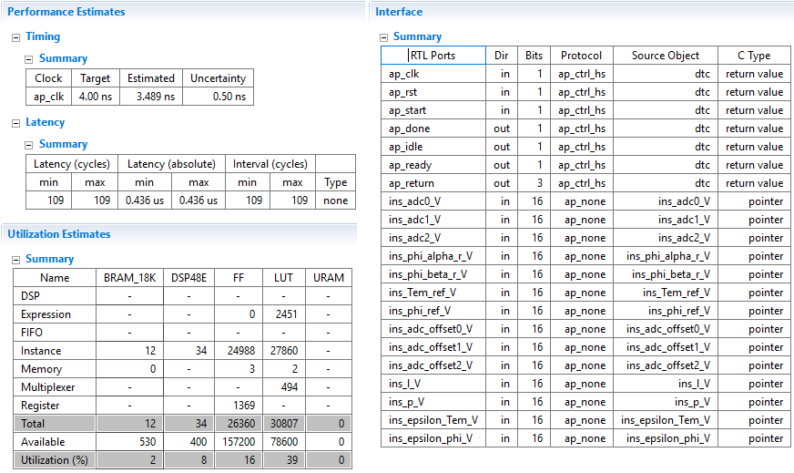
Synthesis result
The HLS synthesis report shown below indicates that the latency of the module is 0.436 µs, which is more than 13 times faster than the CPU-based implementation. It also predicts that the design can run at a clock frequency of 250 MHz.
Integrating the Vivado HLS design in the FPGA firmware
The IP generated from Vivado HLS is instantiated in a sandbox environment. Details on how to edit the firmware of the B-Box are given in PN116. Instructions on how to set up the development environment are given in PN159.
Two simple VHDL modules have been created for the design to comply with the bock-level interface protocol defined in Vivado Design Suite User Guide UG902.
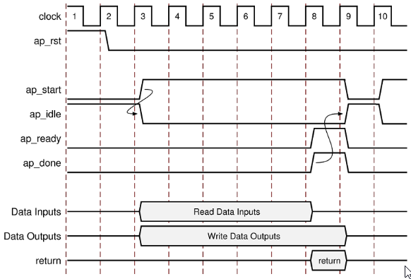
The HLS_start.vhd module asserts the ap_start signal when an adc_done_pulse is detected and clear it when ap_done is asserted.
MY_PROCESS : process(clk_250_mhz)
begin
  if rising_edge(clk_250_mhz) then
    if adc_done_pulse = '1' and ap_idle = '1' then
      i_reg_ap_start <= '1';
    end if;
    if ap_done = '1' then
      i_reg_ap_start <= '0';
    end if;
  end if;
end process MY_PROCESS;

ap_start <= i_reg_ap_start;Code language: VHDL (vhdl)
The HLS_output.vhd module samples the HLS IP pwm output when ap_done is asserted and apply them to the appropriate sb_pwm input.
MY_PROCESS : process(clk_250_mhz)
begin
  if rising_edge(clk_250_mhz) then
    if ap_done = '1' then
      i_reg_pwm(0) <= pwm_in(0);
      i_reg_pwm(2) <= pwm_in(1);
      i_reg_pwm(4) <= pwm_in(2);
    end if;
  end if;
end process MY_PROCESS;

pwm_out <= i_reg_pwm;Code language: VHDL (vhdl)
CPU implementation (using Simulink blockset)
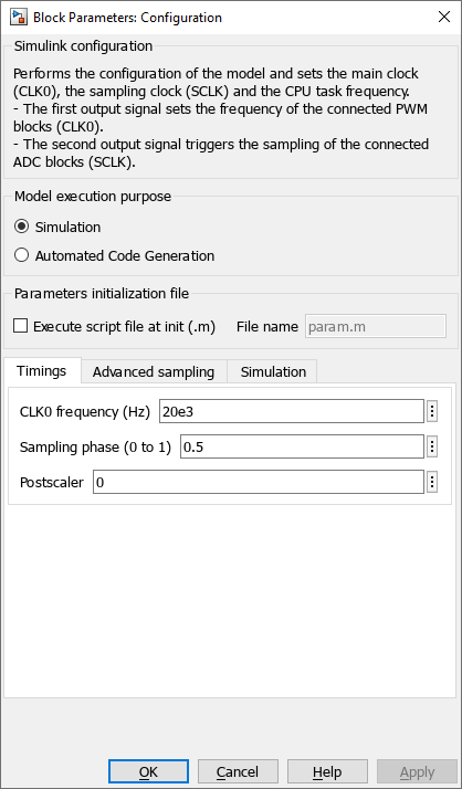
The following configuration is used:
- SBO register 00:
phi_alpha_r(real-time register) - SBO register 01:
phi_beta_r(real-time register) - SBO register 02:
Tem_ref(real-time register) - SBO register 03:
phi_ref(real-time register) - SBO register 04:
l(configuration register) - SBO register 05
p(configuration register) - SBO register 06:
epsilon_Tem(configuration register) - SBO register 07:
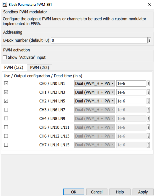
epsilon_phi(configuration register) - SB_PWM: PWM channels 0 to 2 configured with dual outputs with a 1 µs dead time

The PWM output configuration is the following:
Experimental results of the Vivado HLS Direct Torque Control
The FPGA-based approach has been implemented on a B-Box controller and compared with the CPU-based implementation. The setup is the same as in AN004.
The following graphs show a significant reduction of the torque and flux ripples thanks to the shorter control delay enabled by the FPGA-based implementation.