Table of Contents
This note introduces the parallel operation of Grid-Forming Inverters (GFMIs) and provides an implementation example on TPI 8032 programmable inverter with the ACG SDK.
An overview of the hardware architecture and detailed instructions on how to program the device are addressed in getting started with the TPI 8032.
Introduction to parallel operation of Grid-Forming Inverters
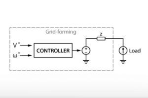
Grid-Forming Inverters (GFMIs) and Grid-Following Inverters (GFLI) are two basic categories of inverters widely used in microgrid systems. Essentially, GFLIs can be considered as current sources with fast dynamic response so that they can rapidly regulate the output to synchronize with the grid. Therefore, the parallel operation of GFLIs is usually simple and costless to achieve. On the other hand, GFMIs can be represented as voltage sources with relatively slow dynamics, and thus require additional considerations to operate in parallel. The parallel operation of GFMIs faces three main challenges:
- GFMIs have voltage controllers to regulate their output voltage. When multiple voltage controllers are connected in parallel to the point of common coupling (PCC), they can “fight” against each other by trying to adjust the voltage at PCC simultaneously, causing oscillations in the grid voltage.
- When operating in standalone mode, each GFMI can have a different output voltage in phase, frequency, and amplitude than the PCC, but this is not possible with parallel inverters. Therefore, a pre-synchronization process is required to match the inverters’ voltages to the PCC voltage before a physical connection can be made. Connecting different voltages without pre-synchronization can cause a significant and potentially destructive overcurrent at the PCC and may cause instability of the voltage controller. Besides, a sudden change of the grid phase and frequency may exceed the allowed Rate of Change of Frequency (RoCoF), causing damage to other devices connected to the grid.
- Power-sharing between the GFMIs in the grid also needs to be considered, especially for the parallel operation of GFMIs with different output power ratings. In general, GFMIs can participate in power-sharing thanks to their ability to set the phase and amplitude of the output voltage. A possible solution to regulate power-sharing explicitly is to use communication between the inverters, but this comes at the cost of increased complexity.
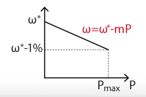
Historically, various solutions have been developed for the parallel operation of synchronous generators. These solutions can also apply to parallel grid-forming inverters. Droop control [1] is a well-established communication-less control strategy that avoids the issue of parallel voltage controllers. Besides, the active and reactive power-sharing between GFMIs can be regulated by the selection of droop coefficients.
In this technical note, the droop controller developed in TN169 will be further developed, with the addition of pre-synchronization of the GFMIs. The effect of droop coefficients on power-sharing will also be addressed.
Pre-synchronization of Grid-Forming Inverters
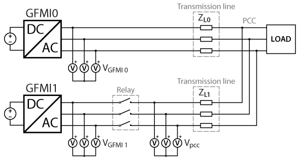
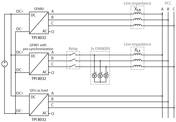
To introduce the process of pre-synchronization, a microgrid consisting of two grid-forming inverters and a load is considered. The grid voltage at the PCC is already established by GFMI0 at the moment when GFMI1 is connected to the grid. To connect GFMI1 properly, its voltage must be synchronized with the PCC voltage before the relay is closed. Indeed, the slow dynamics of the voltage controller do not allow GFMI1 to instantaneously adjust its output voltage to match the PCC voltage. The synchronization prosses taking place before the relay is closed is called pre-synchronization.
To achieve pre-synchronization, the GFMI1 must measure the voltage at PCC \(V_{pcc}\), and regulate its output voltage \(V^{*}\) to match \(V_{pcc}\). This process can be divided into three different steps:
- Pre-synchronization of the voltage amplitude
- Pre-synchronization of the voltage frequency
- Pre-synchronization of the voltage phase
For each of the three steps, a proportional-integral (PI) controller is used to compute corrective terms. Thanks to the integral part, this method can achieve approximately zero error between \(V^{*}\) and \(V_{pcc}\) in a steady state.
Pre-synchronization of amplitude
With the help of droop control, the active and reactive power flows can be decoupled, by controlling the voltage amplitude \(V^{*}\) and frequency \(\omega ^{*}\) independently. Therefore, the pre-synchronization of voltage amplitude can be considered decoupled from that of frequency and phase. [2] The voltage amplitude can be calculated in the stationary reference frame (αβ0) without knowledge of the phase.
The adjustment of the voltage reference can be realized by either directly adjusting the voltage reference \(V^{*}\) or adjusting the reactive power input \(Q\) of the droop controller. However, the latter method may lead to inaccurate reactive power sharing and may also become unusable in the case of a mainly resistive line (i.e. where the reactive power also depends on the frequency).
The control diagram of amplitude pre-synchronization is shown below, with the PI output directly fed forward to the droop controller \(Q-V^{*}\). To avoid affecting the voltage controller when working in standalone mode, a switch is added before the PI controller to keep its input at 0 when pre-synchronization is disabled (sync = 0). Besides, a delay block is added to the feedback of \(V^{*}\) to avoid an algebraic loop.
Pre-synchronization of frequency and phase
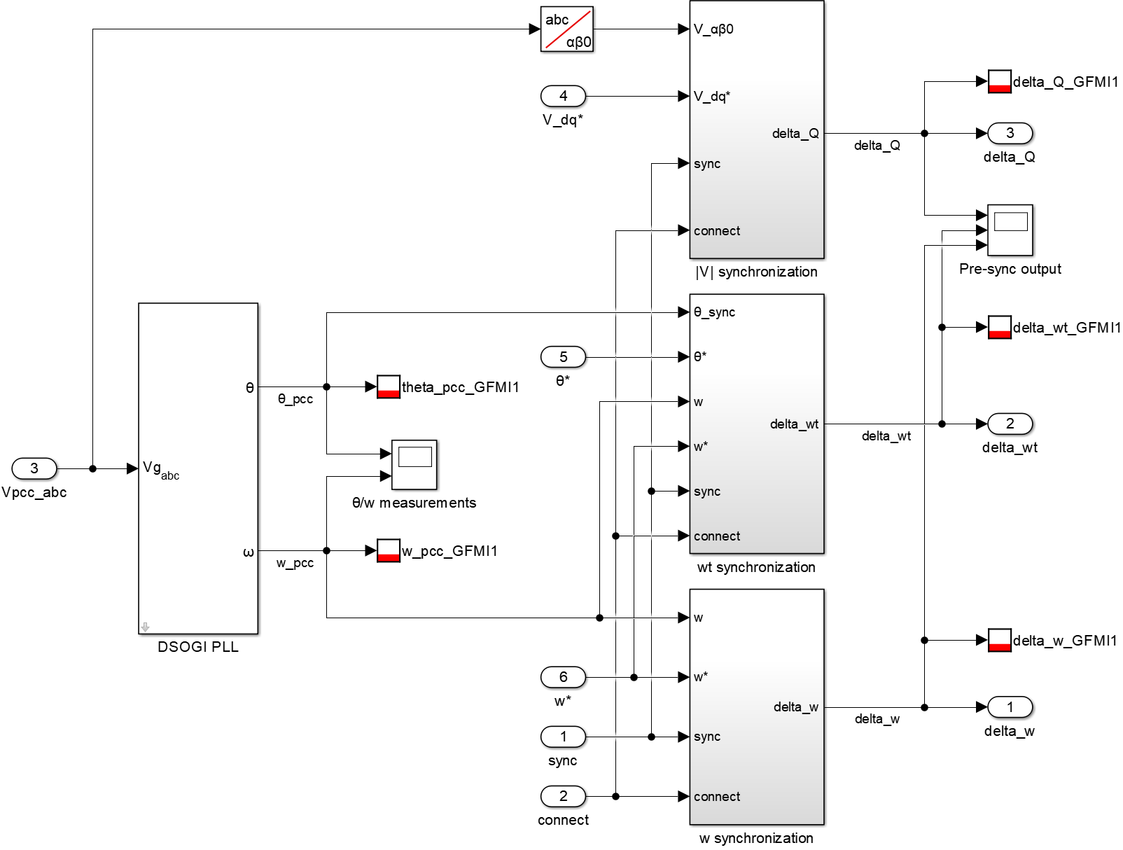
To achieve pre-synchronization of frequency and phase, a PLL is required to measure the frequency and phase of \(V_{pcc}\). This note uses a DSOGI-PLL for better immunity against grid voltage disturbance when the load changes.
The pre-synchronizations of frequency and phase are not independent. In fact, the phase pre-synchronization can be realized by increasing or decreasing the GFMI’s frequency reference [3]. However, this imposes that the phase pre-synchronization can only be started after the frequency pre-synchronization has finished. Otherwise, if the frequency is not synchronized with the grid, both controllers will try to adjust the frequency reference, causing possible oscillation of the frequency.
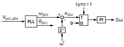
To avoid the oscillation issue, the frequency pre-synchronization is first activated, whereas the phase pre-synchronization only begins when the frequency error is less than a certain threshold \(\epsilon\), which is here set at 0.2Hz. The block diagram of the frequency synchronization is presented below.
For phase pre-synchronization, the phase error is calculated with the sine of the angle difference \(\theta_{pcc} – \theta^{*} \) to avoid discontinuities when either angle wraps to 0 or 2π. For small angle differences, the sine can be approximated to the angle. The block diagram for the phase synchronization is shown below.
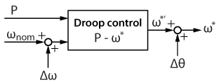
The frequency and phase corrective terms \(\Delta \omega\) and \(\Delta \theta\) are then fed forward to the droop controller \(P- \omega \), as shown below.
Once the errors in voltage amplitude, frequency, and phase are equal to zero, the pre-synchronization is complete, and the relay can be closed. After the relay is closed, the pre-synchronization must be switched off, and the corrective terms must be kept constant and retain the value they had at the end of the pre-synchronization. This can be done by simply setting the input of the PI controllers to zero.
Power sharing between droop controllers
To share active power between both grid-forming inverters, different coefficients \(m_{0}\) and \(m_{1}\) can be used in the frequency droop equations:
$$ \omega_{0}^* = \omega_{nom} – m_0 P_0 $$
$$ \omega_{1}^* = \omega_{nom} – m_1 P_1 $$
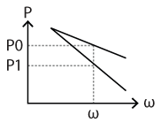
In steady state, since the frequency references of both GFMIs are equal (\(\omega_{0}^*=\omega_{1}^*\)), the power-sharing \(P_0/P_1\) is defined by \(m_{1}/m_{0}\), as illustrated below.
On the other hand, having different droop coefficients can cause oscillations in the frequency in the case of a load step. Considering the active power flow in a transmission line
$$ P\approx3\cfrac{V_1V_2}{X_{l}} \delta, $$
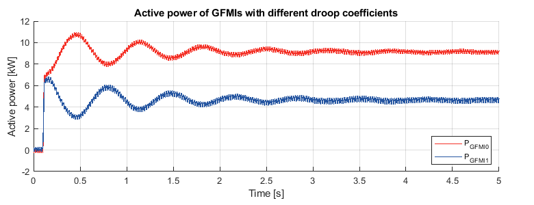
if a load step occurs at \(t = 0\), at \(t = 0^+\) both \(P_0\) and \(P_1\) step to a different value determined by the equation above, and slowly reach their steady-state values. During this transient, the two reference frequencies are different. As a consequence, a phase shift appears between the voltages set by the GFMIs, leading to oscillations of active power between the two inverters. This effect can be observed in the experimental results.
A possible way to dampen the oscillations during the transient is to add a derivative term in the proportional droop controller [4], but this is outside the scope of this page.
Implementation with imperix ACG SDK
The control models available here after are implemented in Simulink using the imperix ACG SDK blockset. The models can both simulate the behavior of the system in an offline simulation and generate code for real-time execution on the TPI 8032. An introductory guide regarding the TPI is addressed in Getting started with the TPI 8032. To run these models, the minimum requirements are:
- Imperix ACG SDK 2024.2 or newer.
- MATLAB Simulink R2016a or newer.
- For simulation only: Simscape Electrical
The pre-synchronization of the grid-forming inverters is shown below.
Experimental setup
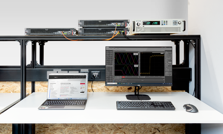
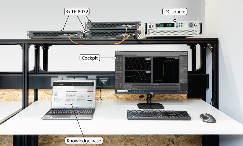
The experimental validation of the parallel operation of grid-forming inverters is carried out with three TPIs used in a master-slave configuration (connected with SFP cables), meaning that they are programmed from the same Simulink model. Two TPIs running as GFMIs are connected in parallel to the PCC through inductors emulating an inductive transmission line. A relay controlled by a GPO port is used to connect GFMI1. A third TPI running as GFLI is connected directly to the PCC as an active load.
The required equipments are:
- 3x TPI 8032 three-phase inverter
- ACG SDK toolbox for automated generation of the controller code from Simulink or PLECS
- 1x bidirectional DC power supply (800V)
- 6x inductors (here 2.2mH)
- 1x three-phase relay
- All the necessary cables
| Parameter | Value |
|---|---|
| Control and switching frequency | 50 kHz |
| Maximum active power P Maximum apparent power S Maximum reactive power Q | 16 kW 22 kVA 15.1 kVar |
| Grid Voltage DC voltage Maximum RoCoF \(\rho\) | 400 VRMS 800 V 1 Hz/s |
| \( \Delta f \) (1%) \( \Delta V \) (10%) | 3.14 rad/s 32.5 V |
| Line inductance | 2.2 mH |
| APC droop coefficient \(m\) APC – LPF cut-off frequency APC – HPF cut-off frequency RPC droop coefficient \(n\) RPC – LPF cut-off frequency | 1.9635e-04 0.3 Hz 0.1 Hz 0.0022 0.3 Hz |
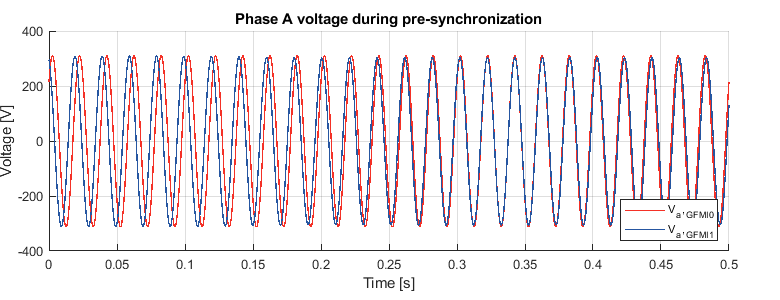
The experiment is performed by running GFMI0 while GFMI1 is still unconnected. Then the GFMI1 starts pre-synchronization with GFMI0. During pre-synchronization, the voltage of GFMI1 is progressively adapted to match that of GFMI0, as shown below.
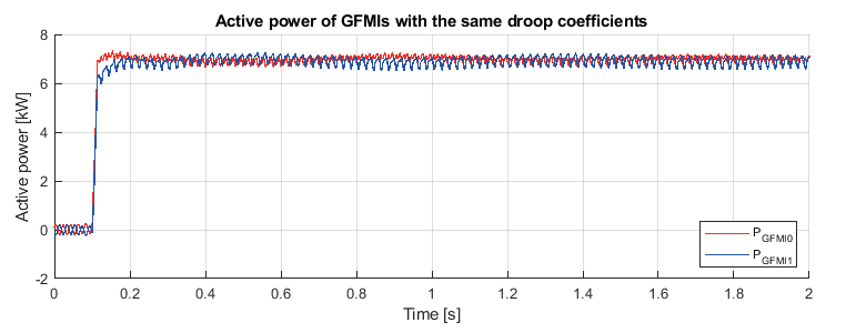
Once the pre-synchronization is done, the relay is closed to connect GFMI1. An active power step of 15kW is performed on the load (GFLI). With the same droop coefficients on GFMI0 and GFMI1, they share the same active power output of 7.5kW.
To study the effect of different droop coefficients on power-sharing, the droop coefficient \(m\) of GFMI1 is doubled. An active power step of 15kW is performed on the load (GFLI).
For the active power sharing, when the system reaches the steady state, the active power of GFMI0 and GFMI1 approximately satisfy \(P_0 = 2P_1 \), which matches well with the theory. Besides, the oscillations discussed previously caused by different droop coefficients can be observed after the load step.
To go further…
In the case of a mainly resistive line, the assumption of an inductive line for P and Q decoupling is no longer valid. To decouple P and Q, a droop control with virtual impedance can be implemented. This is addressed in Virtual impedance for droop control.
To address the lack of explicit inertia in the control, the inertial characteristics of synchronous generators can be emulated through a virtual synchronous generator control. This is addressed in Virtual synchronous generator.
Academic reference
[1] K. De Brabandere, B. Bolsens, J. Van den Keybus, A. Woyte, J. Driesen and R. Belmans, “A Voltage and Frequency Droop Control Method for Parallel Inverters,” in IEEE Transactions on Power Electronics, Jul. 2007.
[2] C. -T. Lee, R. -P. Jiang and P. -T. Cheng, “A Grid Synchronization Method for Droop-Controlled Distributed Energy Resource Converters,” in IEEE Transactions on Industry Applications, Mar.-Apr. 2013.
[3] C. Jin, M. Gao, X. Lv and M. Chen, “A seamless transfer strategy of islanded and grid-connected mode switching for microgrid based on droop control,” in 2012 IEEE Energy Conversion Congress and Exposition (ECCE), Raleigh, USA, 2012.
[4] Y. A. -R. I. Mohamed and E. F. El-Saadany, “Adaptive Decentralized Droop Controller to Preserve Power Sharing Stability of Paralleled Inverters in Distributed Generation Microgrids,” in IEEE Transactions on Power Electronics, Nov. 2008.


