Table of Contents
This page provides a simple first-step guide to building NPC converters and thus focuses on practical aspects. Advanced theoretical considerations are not covered.
In this tutorial, the considered setup is a 3-phase 3-level NPC converter supplied by a DC voltage source and connected to a resistive load. It is controlled by an open-loop controller run in a B-Box RCP. A closed-loop control example for a grid-tie NPC converter is presented in Neutral Point Clamped Inverter (NPC).
What is an NPC converter?
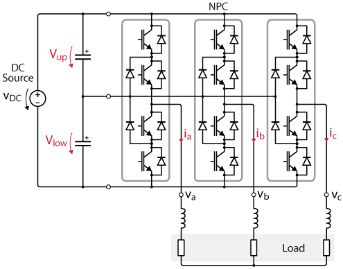
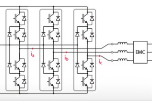
Neutral Point Clamped (NPC) converters are a family of multi-level power converters characterized by clamping diodes, halving the voltage across the power switches. NPC converters were simultaneously introduced by Baker [1] and Nabae et. al [2] in 1981. Today, they remain the best-known and most widespread multi-level converter topology, offering very attractive performance with limited complexity. A typical NPC converter topology is depicted in Fig. 1.
Thanks to their multi-level nature, NPC converters offer better waveform quality than two-level inverters, leading to reduced filtering requirements. They are often present in medium voltage applications, where their higher blocking voltage capability is also an essential requirement. Although N-level NPC converters have also been proposed, the industrial use of NPC-type converters is mostly limited to three-level topologies due to the complex mechanical arrangement of the power devices with a higher number of levels (presence of non-symmetrical elements).
Working principle
Considering each leg, 24=16 different combinations can be generated with the 4 switching components. Besides the full-open state used each time the PWM are deactivated, 3 states are of interest : each phase can be clamped to ±VDC/2 or 0. Other states are not used, since they lead to open or short-circuits.
To reach the states of interest, the following switches must be activated :
| Leg voltage | State | T1 | T2 | T3 | T4 |
| Vup | P | \(1\) | \(1\) | \(0\) | \(0\) |
| 0 | 0 | \(0\) | \(1\) | \(1\) | \(0\) |
| Vlow | N | \(0\) | \(0\) | \(1\) | \(1\) |
where Ti refers to the ith switch for each leg, starting from the top.
Modulation techniques
This example focuses on the basic implementation of two common techniques, namely carrier-based PWM and space vector modulation. Numerous other modulation strategies have been proposed for NPC converters, aiming at optimizing different quantities (e.g. balancing of the neutral point voltage [3]).
Carrier-based PWM
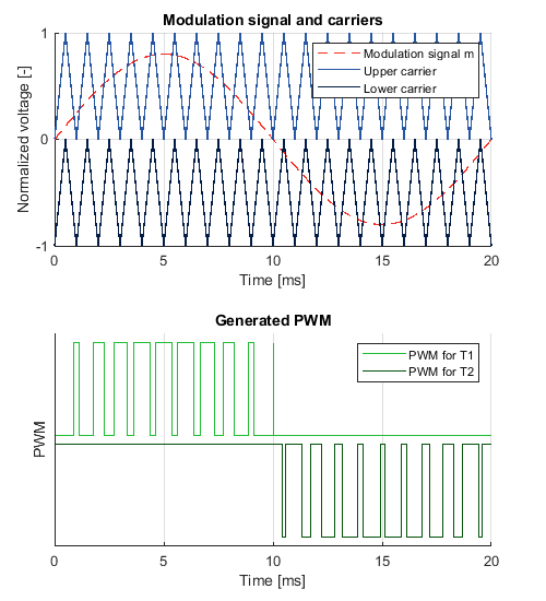
In the carrier-based PWM modulation, the control signals for both commutation cells (T1/T3 and T2/T4) can be generated by comparing a modulation signal m with two carriers, as shown in Fig. 2.
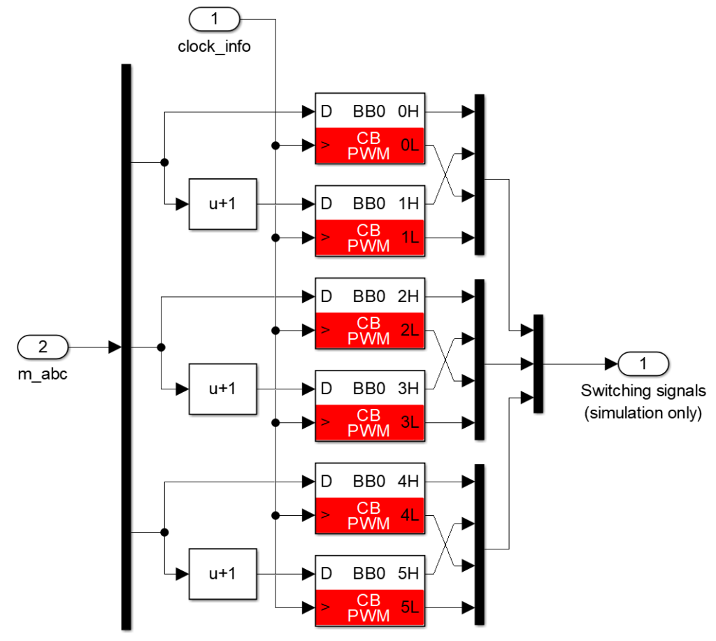
In this example, the modulation signal is shifted by 1 (instead of using a carrier shifted by -1) in the software to ensure compatibility with the CB-PWM block. The Simulink implementation with the CB-PWM block is shown in Fig. 3.
More information about the carrier-based PWM block from the ACG SDK library can be found in CB-PWM – Carrier-based PWM.
Space vector PWM
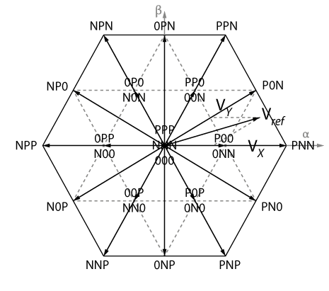
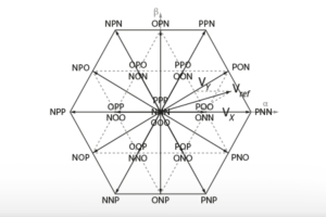
The space vector modulation uses the Clarke transformation, where the voltage (va, vb, vc) is projected into the αβ0-space (often reduced to the αβ-plane when the 0-component is not involved in the control). The αβ-plane is recalled in Fig. 4, where all 3³=27 achievable states (3 phases with 3 possible clamping possibilities) are shown.
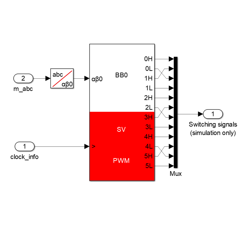
An appropriate repartition among the closest feasible states makes it possible to reach any desired average value within the plane (i.e. within the hexagon). For example, Vref in the Fig. 4 can be obtained by an appropriate repartition among the P00, P0N and PNN states over the period. These calculations are managed by the SV-PWM block, which also automatically generates the PWM outputs, as shown in Fig. 5.
More information about the space-vector modulation can be found in Space Vector Modulation (SVM) and about the Simulink space-vector PWM block in SV-PWM – Space vector PWM.
Physical realization
Hardware requirements
The following list describes the required hardware to follow this tutorial. It comprises imperix products as well as additional components commonly available in power electronics research laboratories.
Imperix Products :
- 1x Rapid Prototyping Controller (B-Box RCP)
- 3x NPC Building Block (PEN8018)
- 1x Control Development Tools for Simulink and PLECS (ACG SDK), with a valid license
Additional components :
- 3x resistors
- 3x inductors
- 1x DC power supply
- Laboratory cables
In the following sections, 8.5Ω resistors, 2.36mH inductors and an 800V power supply are used. Such inductors can notably be found in the passive filter box. A closed rack (type D) is optional, but it is recommended to hold the PEN8018 modules together.
Assembly and wiring
The circuit schematic is depicted in Fig. 6. As indicated, the DC bus capacitors are already included in the PEN8018 modules. The modules also contain two voltage sensors measuring the voltage across the capacitors, and a current sensor for the phase output current.
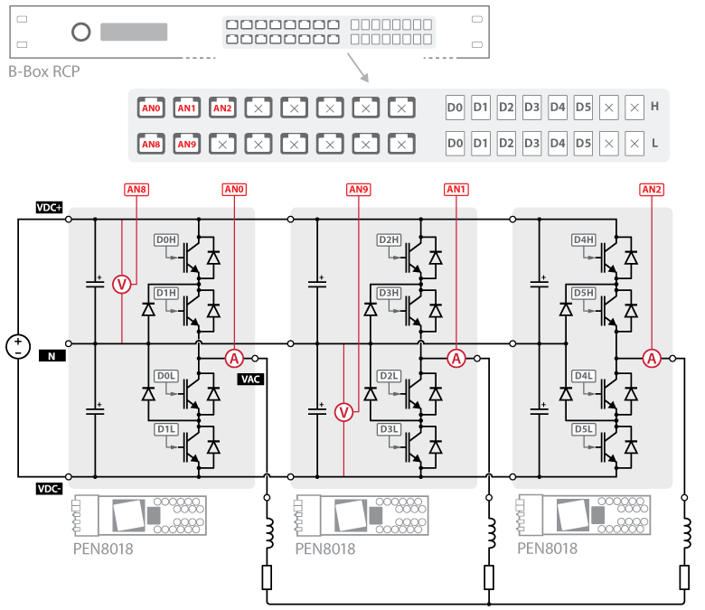
are shown in red and the gating signals in gray.
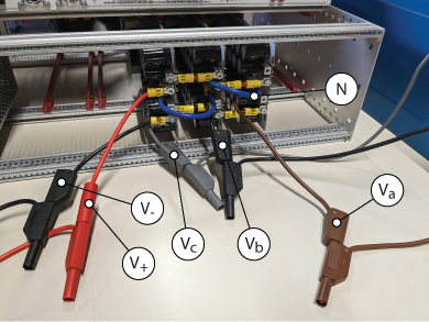
The rear of the converter rack is shown in Fig. 7. For simplicity, it is recommended to follow this specific assembling order :
- prepare the connector for the
VACoutput of each module (indicated asva,vb,vc) and set the jumpers on P6 for the first module (measurement of the upper bus voltage) and on P5 for the second one (measurement of lower bus voltage) ; - slide the modules one by one into the rack and connect the
Nports progressively ; - set the
VDC+andVDC-V+,V-) when all modules are held together in the rack.
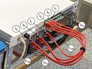
The measurement and control connections are described in Fig. 6 above and should be set up carefully. The measurements are transmitted through RJ45 cables, while the PWM control signals are transmitted through optical fibers (see Fig. 8).
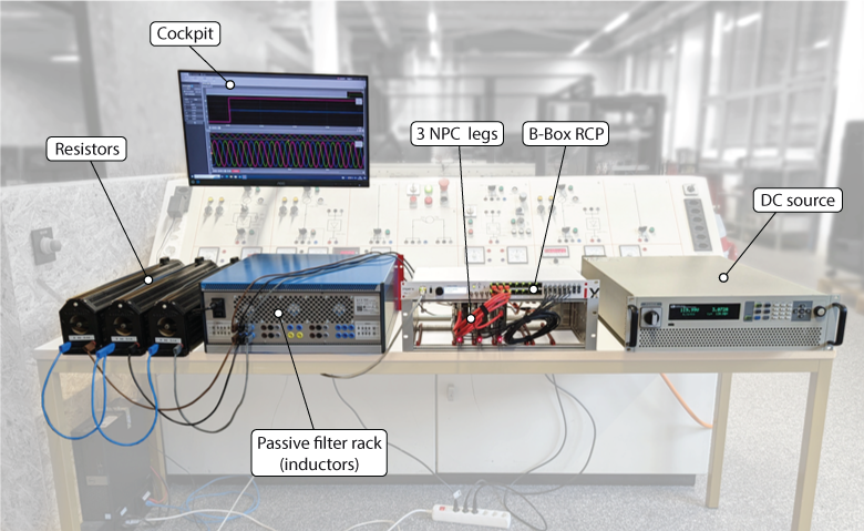
D0H, D1H, D0L and D1L respectively.Then, the DC source terminals can be connected to V+ and V- and the load to the va, vb, vc outputs of the NPC converter. The final setup is shown in Fig. 9, where the components of interest are highlighted.
Configuration of the B-Box front panel
The analog front end of the B-Box contains 16 input channels. For each channel, the following parameters must be configured: the input impedance, the cutoff frequency of the input low-pass filter (if used), the input gain, and the protection thresholds. More information about the analog front-end of the B-Box can be found in Analog front-end configuration on B-Box RCP.
The following table summarizes the parameters to be configured on the B-Box front panel. They are briefly discussed below.
| Channels | Low Impedance | Gain | Filter | Filter Freq. | Limit High | Limit Low | Disable Safety | Save |
| 0, 1, 2 | no | 8 | no | (any) | 7.0 | -7.0 | no | yes |
| 8, 9 | no | 2 | no | (any) | 0.5 | -8.9 | no | yes |
The PEN8018 sensors do not require a low input impedance (only sensors with current output do) : the input impedance must be set to the default high value. Since the input low-pass filter is not used in this example, it will be physically bypassed and the cutoff frequency parameter is therefore irrelevant (no effect).
The phase RMS current is limited to 13.5 Arms in the resistors (more restrictive than the 18A maximal current of the PEN modules and the 30A rating of the inductors). With a sensitivity of -46mV/A and a gain of 8, the expected voltage at the ADC input should span over ±√2 x 13.5 x 0.046 x 8 = ±7V. It remains within the ±10V acquisition range, so the gain can be set to 8.
The absolute maximal rating of each half DC bus is 450V. With a sensitivity of -9.9mV/V and a gain of 2, the expected voltage at the ADC input should not go below -0.0099 x 450 x 2 = -8.9V. This is the highest achievable gain since a gain of 4 or 8 would lead the voltage to exceed the ±10V acquisition range. To avoid undesirable faults due to noise and measurement inaccuracy, a small margin is introduced for the maximal reverse voltage on the capacitor: it is set to -25V (instead of 0). The protection threshold should be set to 25 x 0.0099 x 2 = 0.5V.
Control software
The Simulink model used in this tutorial can be downloaded here below. Both versions only differ in the modulation technique (carrier-based or space vector modulation).
Imperix Power library requires ACG SDK 2024.2 or a later version. To update the ACG SDK, please go to imperix.com/downloads/.
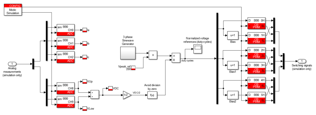
The code can be generated by selecting the Automated Code Generation option within the CONFIG block and then pressing Ctrl+B. At the end of the code generation, a Cockpit session is opened and the user code is automatically loaded/ updated. More information is available in PN138.
In Cockpit, after creating a new project, a scope and a rolling plot can be added to the view from the top bar and variables can be drag-and-dropped from the side panel.
Experimental results
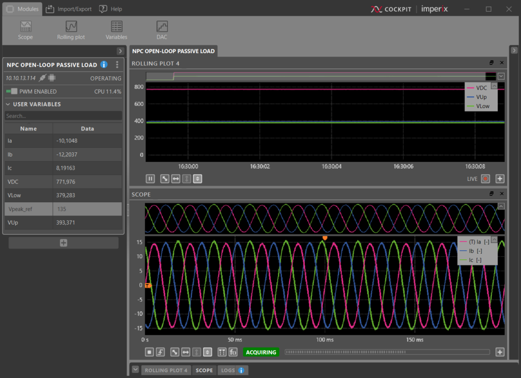
Fig. 11 shows the measured currents obtained with 800V on the DC bus and a 600V peak voltage reference. When using the NPC converter with a passive load, the half-bus voltages are naturally balanced because of the floating neutral.
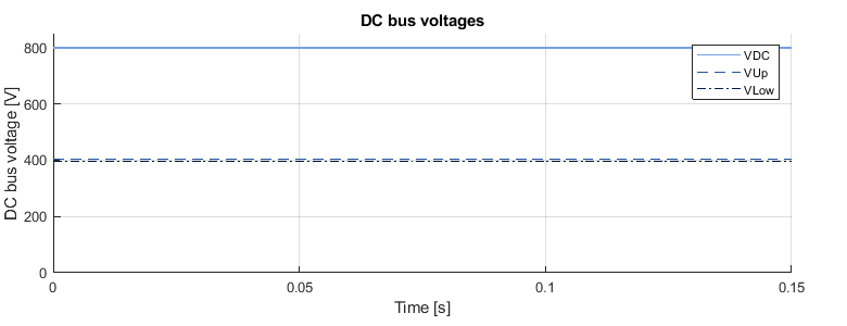
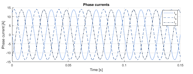
As detailed in Cockpit – User guide, the curves can be exported in .csv and .mat (or even directly as Matlab figures). This makes it possible to process and display them with complete freedom. For example, VDC, Vup, Vlow, and Ia, Ib, Ic curves are shown in Fig. 12.
To go further
A closed-loop control example for grid-tie NPC converter is presented in Neutral Point Clamped Inverter (NPC).
DC bus unbalancing is likely to happen in grid-tie operation. This is due to a non-zero average current going out of the DC bus midpoint, leading to uneven capacitor voltages. Such a situation must be avoided : active balancing of the half DC buses is required. Proper DC bus balancing techniques are described in DC bus balancing of NPC converters.
References
[1] R.H. Baker, “Bridge converter circuit”, U.S. Patent 4270136, May 26, 1981.
[2] A. Nabae, I. Takahashi and H. Akagi, “A New Neutral-Point-Clamped PWM Inverter,” in IEEE Transactions on Industry Applications, vol. IA-17, no. 5, pp. 518-523, Sept. 1981, doi: 10.1109/TIA.1981.4503992.
[3] J. Zaragoza, J. Pou, S. Ceballos, E. Robles, C. Jaen and M. Corbalan, “Voltage-Balance Compensator for a Carrier-Based Modulation in the Neutral-Point-Clamped Converter,” in IEEE Transactions on Industrial Electronics, vol. 56, no. 2, pp. 305-314, Feb. 2009, doi: 10.1109/TIE.2008.2009195.
[4] S. N. Vukosavic, “PWM Voltage Actuator,” in Grid-Side Converters Control and Design (Power Electronics and Power Systems Series). Switzerland: Springer International Publishing, 2018, pp. 54-60. doi:10.1007/978-3-319-73278-7.


