Table of Contents
This technical note gives general insights on the implementation of coordinated control using imperix’s rapid control prototyping solutions. A grid-tied back-to-back three-phase inverter is given as an example, with the idea of showing how two B-Box RCP units would operate and communicate together when controlling such a converter. The provided Simulink files contain the plant model as well as the control implementation using the ACG SDK for both simulation and automated code generation modes.
What is coordinated control?
Coordinated control consists of multiple independent controllers exchanging data to operate one or several power converters. Immediate benefits of this approach over centralized control are the increase in computational power and facilitated control organization. Therefore, coordinated control is an interesting solution in the case of demanding applications. It is often implemented when dealing with separate systems that share common variables, such as back-to-back configurations, multi-terminal systems, distributed drives, etc.
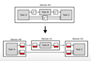
The following illustration gives a general representation of coordinated control. Here, two controllers exchange data (in blue), while acting on their own state variables through dedicated feedback loops (in red).
Control of a back-to-back inverter
A back-to-back configuration often involves a grid-tied rectifier, which controls the DC bus voltage to which an inverter is connected. The output of this inverter is then wired to a controlled load, which may be a variable-speed drive, a grid of another frequency, or any other load which couldn’t be connected directly to the original grid.
For the sake of comparison, three different approaches for arranging the control of such a system are presented below. They correspond to 1) Centralized control, 2) Independent control, and 3) Coordinated control.
The back-to-back converter configuration described in AN005 uses centralized control. In this scenario, the control is indeed implemented on a single controller, which operates the whole back-to-back system. This unique central controller is indeed in charge of retrieving all the analog measurements (grid voltage and current, DC bus voltage, and load currents) and sending the PWM outputs for both converters accordingly.
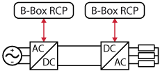
Another solution could be implemented in the form of independent control, where a first controller is in charge of the rectifier and another one of the inverter. It would basically be equivalent to splitting the grid side control and load side control into two controllers. These two controllers being totally independent of each other, the workload would then be also split in two, which would be beneficial when dealing with complex and heavy control algorithms. The drawback is however that the lack of communications would prevent the use of feedforwarding techniques, making the rejection of perturbations more difficult. Also, state variables that are required for both control loops, such as the DC bus voltage, may have to be measured twice.
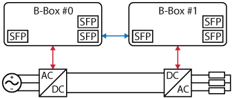
Finally, coordinated control is also an option. It is very similar to the independent control case, with the addition that the two controllers can communicate together. Therefore, shared variables and status information can be sent from one controller to another. Feedforwarding is possible. The number of required measurements can also be reduced. The scheme below summarizes this approach:
Thanks to the data exchanges, the instantaneous inverter power can be feedforwarded to the controllable rectifier. This greatly improves the perturbation rejection on the DC bus voltage. Furthermore, since the measurement of the DC bus voltage can be shared between both converters, it only requires to be measured once.
Communication between coordinated controllers
As aforementioned, the inverter’s output power is feedforwarded to the rectifier’s control to minimize perturbations on the DC bus voltage. However, for the feedforward to be useful, a fast communication method is required. This is why the communication between the controllers is performed using SFP blocks from imperix’s blockset. Indeed, this data transmission method has a low communication latency (around 200ns). Further details on the SFP blocks are given in the note Multi-master feature for distributed networked control systems.
Also note that since the two B-box controllers are connected together using the optical fiber link, their CLOCKs are natively synchronized thanks to imperix’s realSync technology. By extension, the analog inputs sampling, control tasks execution, and the PWM outputs are also all synchronized.
Combining the SFP blocks’ very low latency and the native CLOCKs synchronization the data will arrive before the next task execution, leading to a communication delay of only one control period. This, therefore, allows the proper implementation of the feedforward control.
The two other options for transferring data in between B-boxes are Ethernet and CAN communication, which are both much slower than SFP. They are therefore not suitable for this type of application.
B-Box / B-Board implementation
Software resources
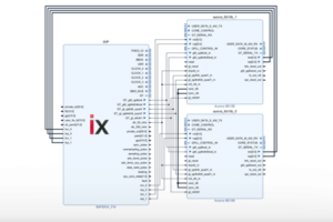
The provided Simulink model implements coordinated control of the back-to-back inverter. The first controller implements a cascaded voltage control of the DC bus. While the second controller regulates the inverter’s load current using a simple vector current control technique.
Experimental results
The rectifier operates with a grid voltage of 110V at 50Hz and regulates the DC bus voltage to 350V. The inverter behaves as expected as shown by the 60Hz sinusoidal output waveform. It is able to track a step in the reference current (in this case from 0 to 12 and back to 5A).
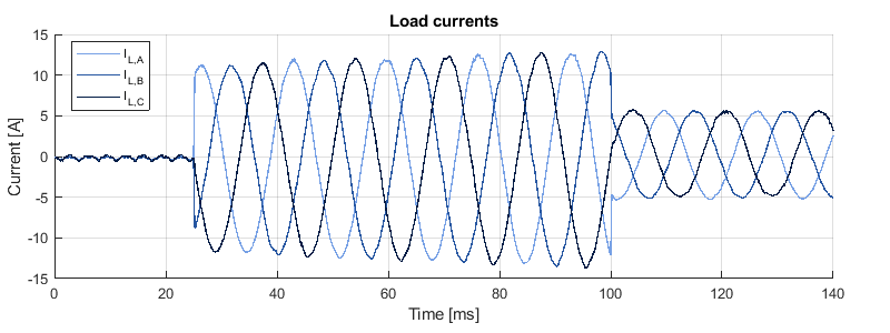
Furthermore, the implemented feedforward clearly improves the perturbation rejection of the DC bus voltage controller as shown below. Indeed, when a step in the reference output current occurs, the DC bus voltage varies significantly (a variation of ±15% is observed) when no feedforward is implemented. On the other hand, almost no perturbation of the DC bus voltage can be observed with the implementation of the feed-forward.
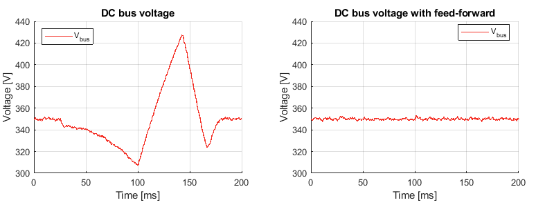
This perturbation can also be observed on the following grid power graphs. The input power is subtracted from the output power to see how well the system can reject perturbations.
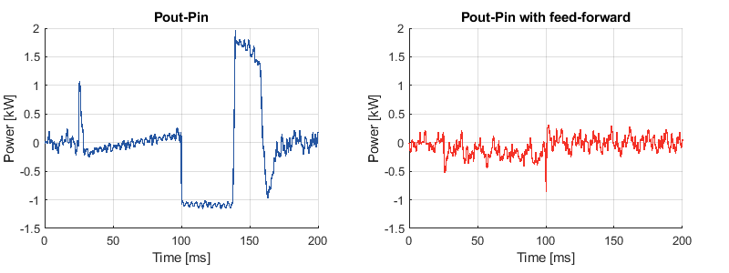
It is clear that, on the left plot, the grid and load power do not compensate each other which then results in perturbations on the DC bus. On the other hand, with the feed-froward of the inverter power, the output and input power compensate each other well.
In the end, implementing coordinated control results in a better performing converter. Having several controllers instead of a single one gives the advantage of better computational power and control hierarchization. On top of that, the communication between the controllers allows to feedforward the inverter’s power to the rectifier which greatly improves the perturbation rejection of the DC bus voltage controller. Furthermore, the drawback of potential communication failure can be mitigated by duplicating the voltage measurement (one voltage sensor for each controller). The converter would then fall back in the independent control mode if the communication link is broken.


