Table of Contents
This note focuses on the multi-master feature which allows executing control codes on multiple imperix power converter controllers interconnected using optical fiber (SFP). The imperix in-house protocol RealSync allows for low latency communication (sub-μs) and high data exchange rate (hundreds of kHz) all while keeping synchronized sampling instants and PWM signals (±2ns).
The Multi-converter system for micro-grid (AN008) example illustrates how the multi-master features can be used to implement coordinates control between TPI8032 programmable inverters. Another use case of multi-master communication is presented Coordinated control of a back-to-back inverter (TN155).
Imperix distributed converter control solutions
The latest SDK is available on the download page.
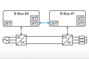
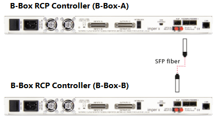
The imperix proprietary RealSync communication protocol allows connecting multiple devices using SFP fibers, as shown below with two B-Boxes RCP. The same applies for the B-Board PRO, and the Programmable Inverter.
When imperix devices are interconnected:
- All CLOCKs are natively synchronized and by extension the analog inputs sampling, control tasks execution, and the PWM outputs are all synchronized.
- In the event of a fault anywhere one the network, the PWM outputs of all devices are immediately disabled with node-to-node propagation delay of less than 180ns.
A multi-device system can operate in different modes:
- In master-slave mode (aka I/O extension mode) the control algorithm runs on the master unit’s CPU, while the slave devices operate as I/O extension units, with only their FPGAs active. Slaves are addressed transparently from the peripheral’s block in Simulink/PLECS/C++ code, using the device ID parameter (indicated as BB0, BB1, etc. on the blocks).
- In multi-master mode, each master device has its CPU running. Since each CPU code requires its own Simulink/PLECS/C++ model, communication between devices must be handled explicitly using communication blocks. The CAN or UDP blocks can be used to exchange data, but using the SFP blocks offers superior performance (sub-microsecond latency and exchange rates in the hundreds of kHz). Detailed information about the SFP blocks can be found in a later chapter.
- In multi-master with slaves (or combined mode) both modes are mixed, allowing for the implementation of a wide range of distributed converter control techniques.
Illustration of a master-slave scenario
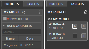
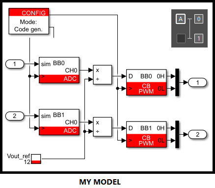
Illustration of a master-master scenario
The meaning of the different numbers and letters is explained below.
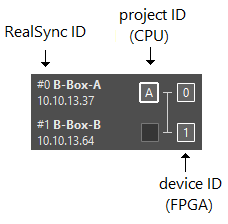
- The device ID (0, 1, …) is the number used to address the FPGA
- The project ID (A, B, …) shows where the generated code is running
- The RealSync ID (#0, #1, …) is the number uniquely identifying a device in a RealSync network
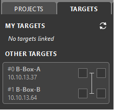
Setting up a multi-master system
To set up multi-master operation, as shown in the video below, the following steps must be followed:
- Create one model for each master, using Simulink, PLECS or the C++ SDK.
- Build the models. After the first successful build a project is automatically created in Cockpit.
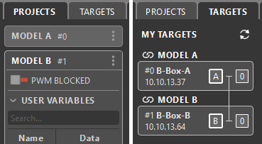
- Once the projects are created, proceed with linking each project to its respective device as illustrated on the screenshots below. Once a device is linked to a project, it becomes a master, identified by a letter (e.g., A, B, etc.).
Multi-master using Simulink
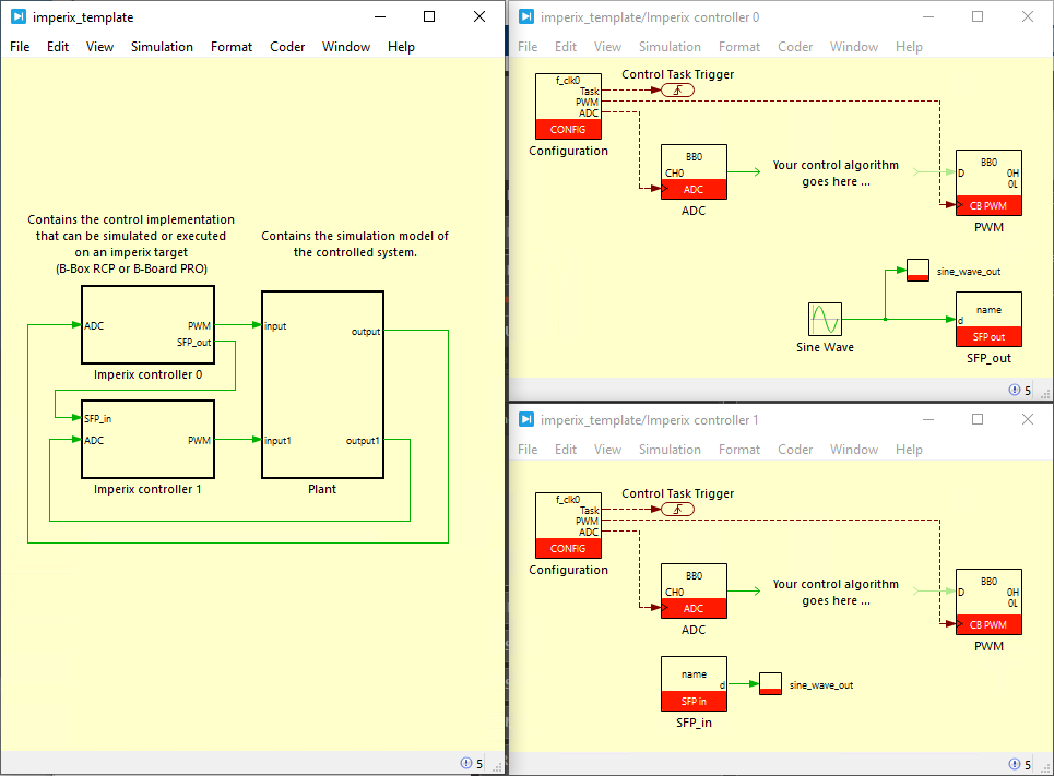
The Simulink template provided below simplifies the development of distributed control using the multi-master feature. This template aims to facilitate distributed control development. It uses Simulink Model references to support both simulation and code generation in the same development environment.
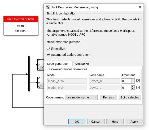
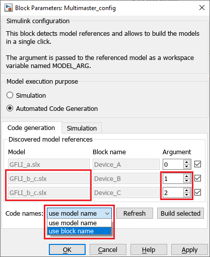
The image below shows the Multimaster config block provided in the template.
- The user can add additional model references and even reference the same model multiple times. Clicking the Refresh button will update the list of model references.
- If a model is referenced multiple times, the option use block name must be selected to avoid naming conflicts.
- Changing the model execution purpose in the multi-master config block will apply the change to all referenced models.
- Clicking Build selected will generate and build the codes for all the models that are checked in the list.
Exchanging data between the models
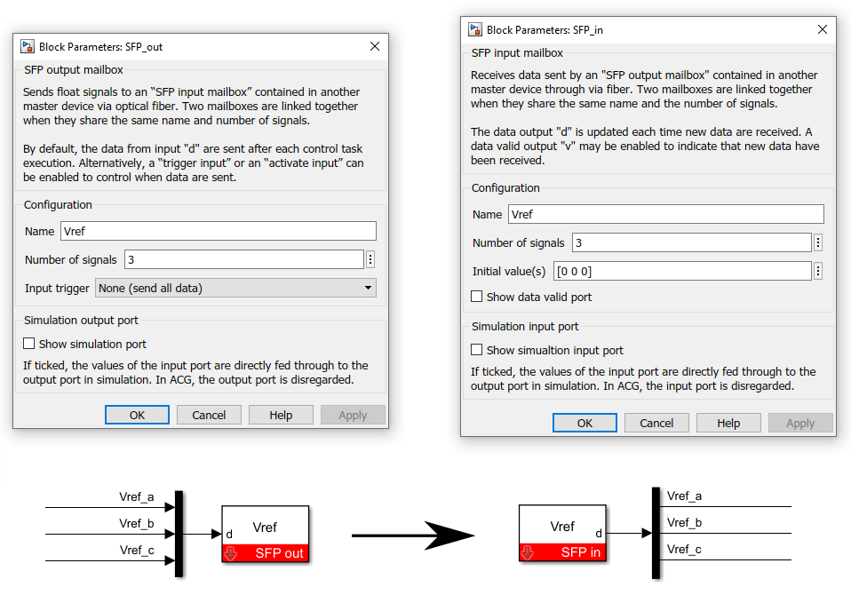
The SFP blocks shown below allow exchanging data between models via the optical fiber links. These SFP blocks work in pairs: an SFP output mailbox must be placed in one model, and an SFP input mailbox in another. The two mailboxes are automatically linked together when they share the same name and number of signals.
By default, the SFP output mailbox sends data at each control period. However, the user can enable a trigger input to control precisely when data is sent. On the SFP input mailbox side, a data valid output port indicates when new data has been received.
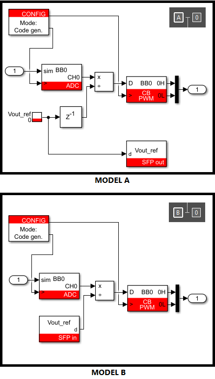
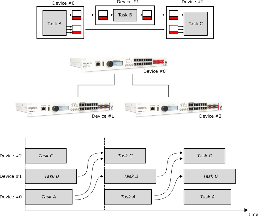
The image below illustrates an example where three control models are running on three B-Boxes and exchanging data using SFP blocks. The control models operate at the same control frequency and share the same sampling phase. Consequently, the sampling occurs at the same time on all devices and the three control tasks start simultaneously. Thanks to the low communication latency (~200 ns per hop), the transferred data arrives before the next task execution, resulting in only one control period delay. Note that the two mailboxes can be located on any device within the network, the devices do not need to be adjacent.
Referencing the same model multiple times
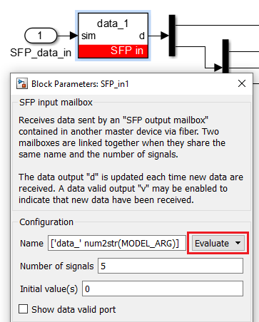
In some applications it might be useful to execute the same model on multiple devices. As illustrated below, it is possible to reference the same Simulink model multiple times. In that case, selecting the use block name option is necessary to prevent code name conflicts. The MODEL_ARG workspace variable can be used when models need to behave differently. It can also help preventing SFP mailboxes naming conflicts.
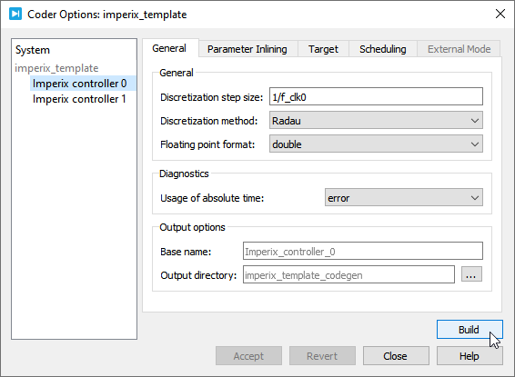
Multi-master using PLECS
Multi-master development using PLECS is more straightforward. The user can start from the provided template and duplicate the Imperix controller subsystem.
The Imperix controller subsystems are listed on the Coder Options page. ([Ctrl+Alt+B] or click on Coder > Coder Options). The user must select the subsystem for which they wish to generate CPU code and then click Build.