Table of Contents
The SFP ports on imperix controllers are typically used for interconnecting devices in a RealSync network. However, when customizing the FPGA firmware, imperix designed the system to allow these SFP ports to be repurposed for other communication protocols. Aurora 8B/10B or Aurora 64B/66B can be used to communicate with hardware-in-the-loop (HIL) simulators that support the Aurora protocol, such as OPAL-RT, TYPHOON HIL, SPEEDGOAT and RTDS.
This note provides an example of loopback communication using the Aurora 8B/10B protocol over a fiber optic link. It provides a step-by-step guide demonstrating how the Aurora 8B/10B protocol can be seamlessly integrated into the imperix controller FPGA. An example of Aurora 64B/66B is also provided.
Required hardware to follow this example:
- 1x imperix controller with SFP ports
(B-Box RCP, B-Board PRO or TPI8032) - 1x 10G SFP cable
Required software:
- Xilinx Vivado 2022.1 or later.
Installation guide available here. - FPGA sandbox template 3.10 or later.
Available on the FPGA download page. - C++ or ACG SDK version 2024.3 or later.
Available on the SDK download page.
What is Aurora ?
Aurora is a serial link layer communication protocol developed by Xilinx/AMD. The protocol is open and provides lightweight, high-speed point-to-point communication between devices. Implementing Aurora communication is particularly useful for establishing high-throughput, low-latency communication with other power controllers or HIL simulators. The protocol is available in two versions: Aurora 8B/10B and Aurora 64/66B. Aurora 8B/10B provides lower latency while Aurora 64B/66B provides higher bandwidth.
Aurora 8B/10B loopback example
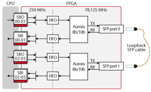
For demonstration purposes, a loopback connection is established between two ports on the same controller, as shown in the diagram below:
- SBI and SBO blocks are used to move data between the CPU and the FPGA.
- FIFOs are used to move data between the IXIP clock domain (250 MHz) and the Aurora communication clock domain (78.125 MHz in this example).
- Aurora 8B10B IPs encode/decode data.
- TX/RX serial links are connected to physical SFP ports to transmit data over the optical fiber.
Vivado project
The Vivado block design of the Aurora 8B/10B loopback example is provided below.
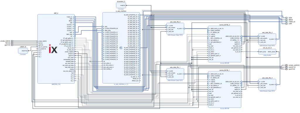
The following zip file contains scripts to automatically generate this design.
To generate the design using the script, please do the following:
- Download the FPGA sandbox template 3.10 or later, available on the FPGA download page
- Unzip it and save the content somewhere on the PC
- Rename the folder to something more explicit
- Download Aurora_8b10b_example_gen_scripts.zip using the button above
- Unzip it and copy the content to the scripts folder of the FPGA sandbox template
- Set the vivado_path variable to match the Vivado version installed on the PC
- Double-click on create_aurora_8b10b_example.bat
Windows Defender SmartScreen may display a warning pop-up. Simply click More info, then Run anyway.
The Vivado Aurora 8B/10B project will be created and configured. The step-by-step section below explains how to recreate it manually.
MATLAB model
The model below is used to test the design. It generates a sinusoidal waveform and sends it to the FPGA using SBI 0 and 1. It reads the received on SBO 2 and 3. Probe variables are used to observe the sent and received signals on Cockpit.

Experimental results
Observing the signals on Cockpit validates that the data sent on port SFP 0 using Aurora 8B/10B is properly received on port SFP 1.
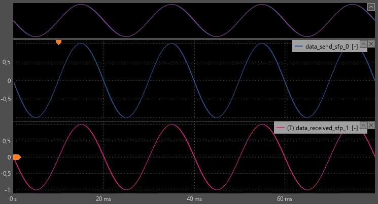
Thanks to the Aurora 8B/10B low latency, there is a delay of 2 control task periods between sending and receiving data.
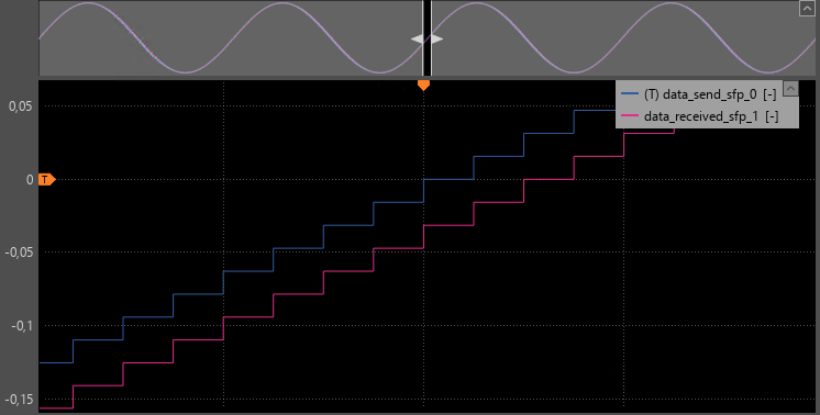
Using the Integrated Logic Analyzer (ILA) in Vivado, the propagation delays of the data in the FPGA can be measured. With a lane rate of 3.125 Gbps, the total measured delay is 560 ns. It consists in:
- 84 ns for the TX FIFO data
- 424 ns for the Aurora communication
- 52 ns for the RX FIFO

Step-by-step procedure to create the Aurora 8B/10B loopback example
Instantiating the Aurora 8B/10B IP
The first step is to instantiate 2 Aurora IPs. The Aurora 8B/10B IP is available for free from the Vivado IP Catalog.

Configuring the Aurora 8B/10B IP
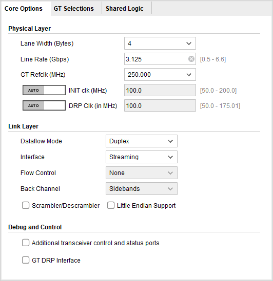
The screenshots below show the settings used in this example. The two following parameters must be set to specific values to work on imperix hardware:
- GT Reflck must be set to 250 MHz, because the clock is generated outside of the FPGA
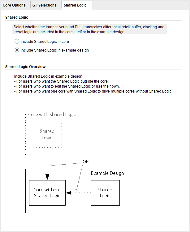
- “include Shared Logic in example design” must be checked, because the Shared Logic is already instantiated inside imperix firmware
The other Core Options settings can be modified freely. Below are the settings used in this example:
- A lane width of 4 Bytes was chosen to be easily interfaced to the AXI-Stream interface.
- The default line rate of 3.125 Gbps was kept. This will result in a data clock of
line_rate * 0.8 / lane_width_in_bits = (3.125 Gbps * 0.8) / (32 bits) = 78.125 MHz - In this example, making packets is unnecessary, so the interface is set to streaming mode.
Other Core Options settings are not detailed in this note and are left as defaults.
Configuring the imperix IP
The second step is to configure the imperix firmware IP to make the SFP ports available from the sandbox. In this example, SFP 0 and 1 are used.
This makes the following ports visible on the imperix IP.
- TX and RX signals are the differential serial signals connected between the transceiver and the physical SFP ports.
- The GT interface gives access to the shared logic instantiated in the imperix IP.
Connecting the clocks of the Aurora 8B/10B IP
The Aurora IP provides a tx_out_clk (78.125 MHz in this example), which is used as the user_clock. A BUFG buffer is required between tx_out_clk and the clock inputs. The init clocks and DRP clocks are connected to clk_50_mhz provided by the imperix firmware IP.
To learn more about the different clocks, please refer to the Aurora 8B10B IP and the GTX transceiver user guides.
Connecting the data interfaces of the Aurora 8B/10B IP
The AXI-Stream interface module (ix_axis_interface) is used to exchange data with the Aurora IPs. As the AXI-Stream interface module and the Aurora IPs are not in the same clock domain, AXI4-Stream Data FIFO with independent clocks are used to manage the clock domain crossing. The figure below shows how the FIFOs are connected in the system.
To learn more about the AXI-Stream interface module, please refer to the getting started page.
Connecting the shared logic interface of the Aurora 8B/10B IP
The following signals, connected to the shared logic of Aurora, must be connected between the GT interface of the imperix firmware IP and each Aurora IP:
- gt0_qplllock
- gt0_qpllrefclklost
- gt_qpllclk_quad1
- gt_qpllrefclk_quad1
- gt_refclk1
Connecting the TX/RX signals of the Aurora 8B/10B IP
Finally, the rxn, rxp, txn, and txp signals of each Aurora IP must be connected to the corresponding pins of the imperix firmware IP to map each Aurora IP to a physical SFP port on the board.
Finally, the bitstream can be generated and loaded in an imperix controller, as explained on the getting started page.
Aurora 64B/66B loopback example
In a similar manner to the Aurora 8B/10B example, it is possible to configure an Aurora 64B/66B communication on SFP ports. This section details the steps to adapt the Aurora 8B/10B example described in the previous section to use an Aurora 64B/66B communication.
The Vivado block design of the Aurora 64B/66B loopback example is shown below.
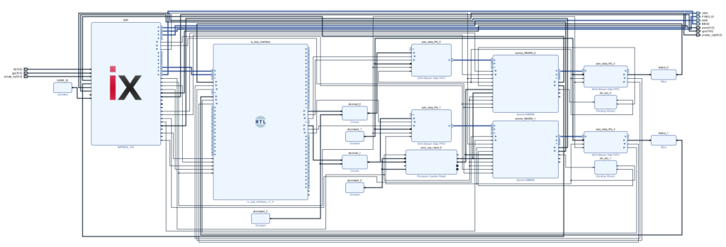
The following zip file contains scripts to automatically generate this design.
To use the script , please follow the same instructions as for the 8B/10B example. Since this example has the same behavior as the 8B/10B example, it is possible to reuse the MATLAB model above to test the design.
Instantiating the Aurora 64B/66B IPs
The two Aurora 8B/10B IPs are replaced by Aurora 64B/66B IPs.
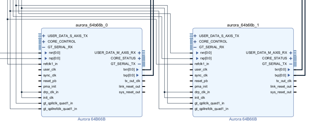
The connections of the following signals are the same as for the Aurora 8B/10B IP:
- The init and DRP clocks are connected to clk_50_mhz, which is provided by the imperix firmware IP.
- The shared logic signals (refclk1_in, gt_qpllclk_quad1,gt_qpllrefclk_quad1) are connected to the GT interface of the imperix firmware IP.
- The rxn, rxp, txn and txp signals are connected to the imperix firmware IP.
The configuration of the Aurora 64B/66B IP follows the same rules as the Aurora 8B/10B IP:
- GT Reflck must be set to 250 MHz as the clock is generated outside the FPGA.
- “Include Shared Logic in example design” must be checked, because the shared logic is already instantiated inside the imperix firmware.
- The other settings can be changed freely.
Connecting the Aurora 64B/66B IP clocks
A Clocking Wizard is instantiated for each Aurora 64B/66B IP to generate the user clock and the sync clock from the tx_out clock. The Clocking Wizard is configured as follows:
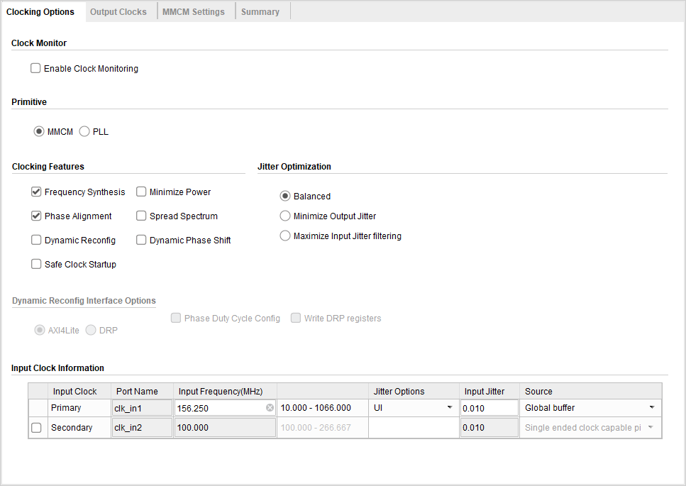
- The primitive is set to MMCM.
- The input frequency is set to the tx_out_clk frequency of the Aurora 64B/66B IP. This frequency can be calculated from the line rate: tx_out_clk_freq = line_rate / 32. With a line rate of 5 Gbps we get a tx_out_clk of 156.25 MHz.
- The source is set to Global buffer.
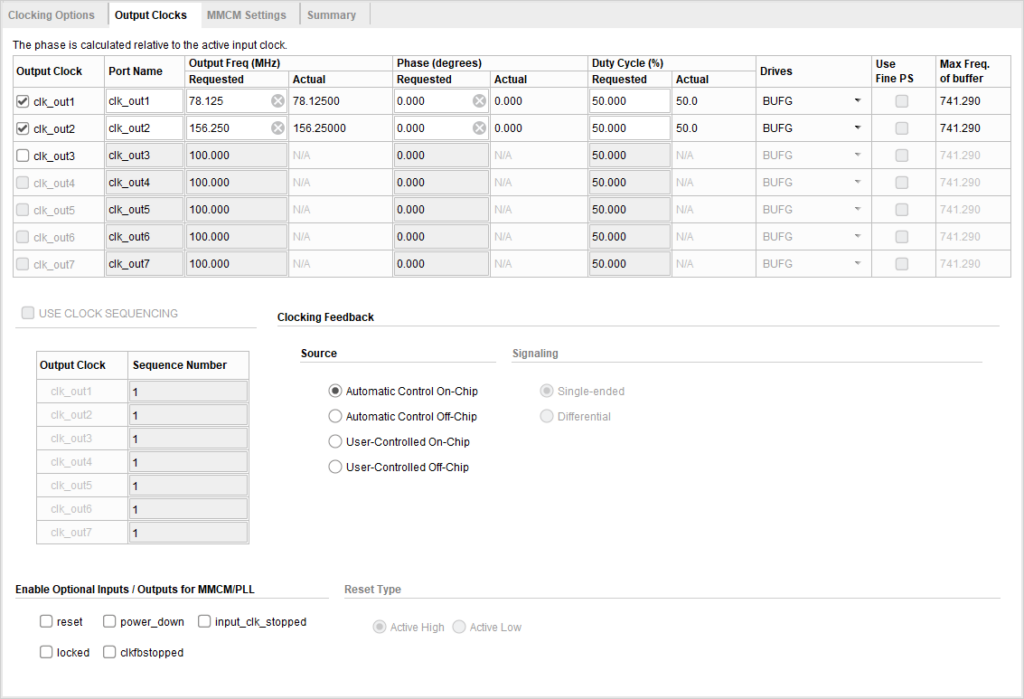
- The frequency of output 1 is set to half the frequency of tx_out_clk, in this example 78.125 MHz.
- The frequency of output 2 is set to the same frequency as tx_out_clk, in this example 156.25 MHz.
- The drive buffer for both outputs is set to BUFG .
The Clocking Wizards are connected to the Aurora 64B/66B IP as follows:
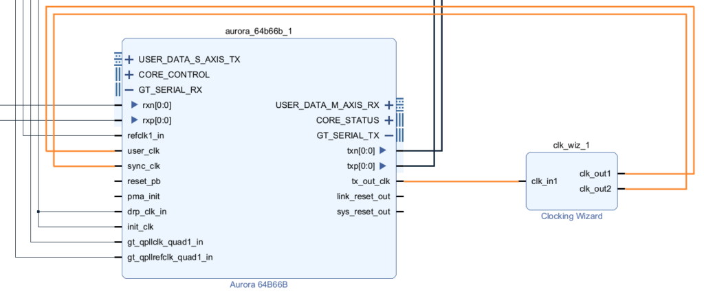
- The input of the Clocking Wizard is connected to tx_out_clk on the Aurora 64B/66B IP.
- Output 1 of the Clocking Wizard is connected to user_clk on the Aurora 64B/66B IP.
- Output 2 of the Clocking Wizard is connected to sync_clk on the Aurora 64B/66B IP.
Connecting the Aurora 64B/66B IP reset signals
Unlike the Aurora 8B/10B IP, the Aurora 64B/66B must be properly reset during initialisation to function properly. In this example, the reset is handled by the Processor System Reset IP provided by Xilinx/AMD. The IP is used with default settings and connected as follows:
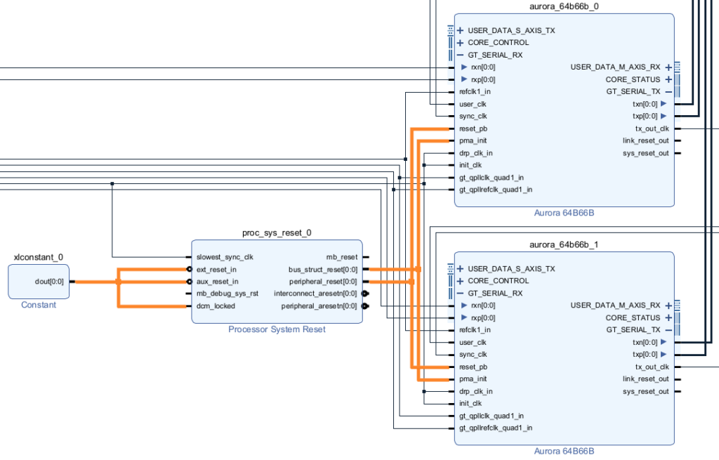
- The slowest_syn_clk input of the Processor System Reset IP is connected to the init_clk of the Aurora 64B/66B IP.
- The ext_reset_in, aux_reset_in and dcm_locked inputs are connected to a constant set to 1.
- The pma_init signal of the Aurora 64B/66B IP is connected to the bus_struct_reset.
- The reset_pb signal of the Aurora 64B/66B IP is connected to the peripheral_reset.
Connecting the data interfaces of the Aurora 64B/66B IP
Since the Aurora 64B/66B provides a 64-bit data interface, 64-bit FIFOs are used and the data from the AXI stream interface is padded with 32 additional zeros to comply with the FIFOs’ width. Additional zeros are then removed in the incoming stream before being fed back to the AXI stream interface.


Finally, the bitstream can be generated and used in the same way as in the Aurora 8B/10B example.
Going further
The page high-level synthesis for FPGA developments shows how automated code generation tools such as Model Composer and Vitis HLS can be used to facilitate the development of FPGA modules. Like the Aurora 8B/10B IP, they use AXI4-Streams to move data around.
The FPGA development on imperix controllers summarizes all the other FPGA-related pages.


