Table of Contents
This document provides instructions on how to interface an incremental encoder with a B-Box RCP or a B-Board PRO and how to read the motor rotor position using the angle decoder modules. It also presents a simple and effective way to derive an angular velocity from the measured angle.
Technical resources
- B-Box datasheet
- B-Board datasheet
- DEC – Angle decoder function block
- Implementation example: Field-oriented control of permanent magnet synchronous machine
Incremental encoder
In drive applications, the knowledge of both the rotor angular position and angular speed is a central point to achieve oriented vector control and robust speed control. These two variables can either be measured (sensored) or estimated (sensorless).
In sensored applications, one possible way of measuring the rotor position is by using incremental encoders. They notably differ from absolute encoders in that the latter provides an absolute position, often coded in Gray code. Incremental encoders, on the contrary, provide only incremental position changes and an interface is needed to compute the rotor absolute position. This is the purpose of the decoder module available on the B-Box RCP and B-Board PRO.
The most common incremental encoders are quadrature encoders. They produce quadrature signals A and B, allowing to deduce the direction of rotation, depending on which signal is leading. Optionally, a reset signal Z is present to provide an absolute position (one pulse per turn). Finally, to offer more robustness against perturbations, some encoders provide also the complementary signals \A, \B and \Z.
References
[1] Encoder Products Company, “WP-2011: The Basics of How an Encoder Works“, White paper, March 2018
[2] Autonics, “Rotary encoders – Technical description”, Feb 2018
Decoder
The decoder modules present on the B-Box RCP and B-Board PRO are meant to decode the angle information from a quadrature incremental encoder, with or without Z signal and with or without complementary signals. They offer the following configuration parameters:
| Parameter | Possible values | Remark |
|---|---|---|
| Input mode | Single-ended / Differential | If Differential, the complementary signals are also considered |
| Pulse per rotation (ppr) | Between 1 and 65536 | Must correspond to the encoder specifications |
| Reset mode | Maximum value / Z input | If Maximum value, the decoder counter is reset when it reaches the ppr value. Otherwise, it’s reset on a rising edge of the Z signal. |
| Direction | Clockwise / Counterclockwise | If Clockwise and A is leading, the angle increases |
| Invert input signals | No / Yes | If Yes, all the inputs signals are inverted |
The decoder driver is implemented in FPGA with the following logic:

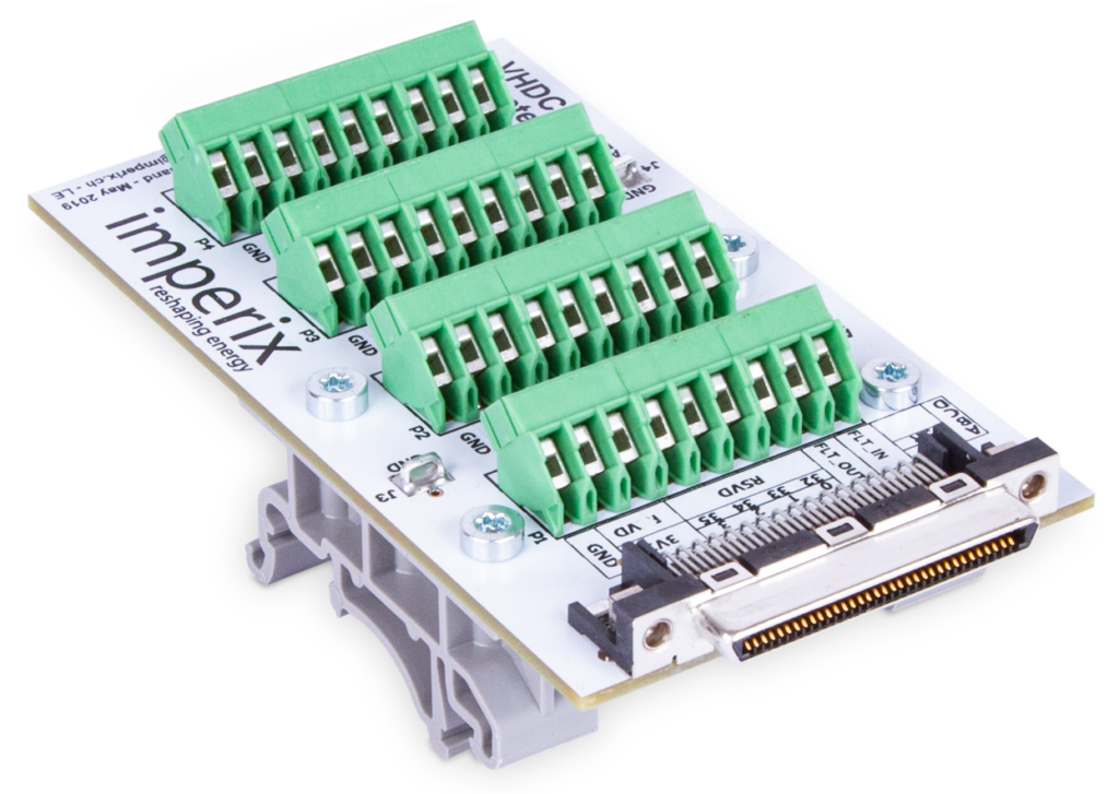
There are a total of 4 decoder modules on each B-Box or B-Board. The encoder signals have to be connected to the GPI inputs of the device, using the following pins:
| Conn. pin | GPI signal | DEC signal |
|---|---|---|
| A2 | GPI 0 | A0 |
| A3 | GPI 1 | B0 |
| A4 | GPI 2 | Z0 |
| A5 | GPI 3 | A1 or \A0 |
| A6 | GPI 4 | B1 or \B0 |
| A7 | GPI 5 | Z1 or \Z0 |
| Conn. pin | GPI signal | DEC signal |
|---|---|---|
| B2 | GPI 8 | A2 |
| B3 | GPI 9 | B2 |
| B4 | GPI 10 | Z2 |
| B5 | GPI 11 | A3 or \A2 |
| B6 | GPI 12 | B3 or \B2 |
| B7 | GPI 13 | Z3 or \Z2 |
Computing angular speed
The angular speed can be derived from the angle information, directly inside the user application. The angular speed being the derivative of the angle, it can be computed as the variation of the measured angle between two consecutive samples:
$$ \omega_m(k) = \displaystyle\frac{\theta_m(k)-\theta_m(k-1)}{T_s} $$
As the measured angle is in the range \(\left[ 0; 2\pi\right]\), its value jumps from \(2\pi\) to \(0\). These discontinuities can be compensated as follows:
$$ \omega_m(k) = \left\{\begin{array}{ll} (\theta_m(k)-\theta_m(k-1)+2\pi)/T_s & \text{if } \theta_m(k)-\theta_m(k-1) < -\pi\\ (\theta_m(k)-\theta_m(k-1)-2\pi)/T_s & \text{if } \theta_m(k)-\theta_m(k-1) > \pi\\ (\theta_m(k)-\theta_m(k-1))/T_s & \text{otherwise} \end{array}\right. $$
Oftentimes, the speed value needs to be filtered to minimize the effect of the quantization error of the angle encoder. A simple filtering solution is by using an IIR filter, with the following transfer function:
$$ H(z) = \displaystyle\frac{\alpha}{1+(\alpha-1)z^{-1}} $$
The \(\alpha\) parameter depends on the filter cutoff frequency \(f_c = 1/(2\pi t_c)\) and the sampling period \(T_s\) (i.e. execution rate of the filter):
$$ \alpha = \displaystyle\frac{T_s}{t_c+T_s} = \frac{2\pi f_c T_s}{1+2\pi f_c T_s} $$
Initialization of the rotor position
The Z signal of an incremental encoder gives a reference for the rotor position, allowing the decoder to provide an absolute rotor angle, once initialized. However, there is no guarantee that this reference corresponds to 0 rad electrically. A possible way to initialize the rotor position is to proceed manually:
- Before energizing the converter, one complete rotation of the rotor is done manually to reset the decoder counter with a pulse on the Z signal.
- The converter is energized (DC bus charged) and a current (typically 0.5 p.u.) is applied to the phase a of the motor. This will align the rotor with one of the poles of phase a.
- The offset of the measured angle is compensated, in order to measure 0 rad when the rotor is aligned with phase a (i.e. when the permanent magnet flux is completely along the α-axis).
Other initialization methods are of course possible. The above procedure has the advantage of being extremely simple to set up and is applicable to most drive testbenches.
B-Box / B-Board implementation
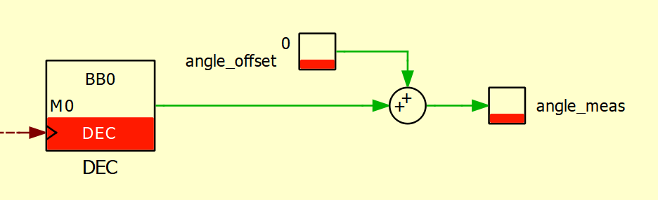
Simulink
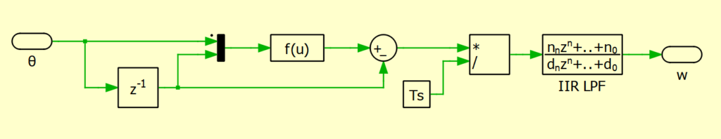
The decoder block (DEC) provides the measured angle. As such, the speed can also be derived as follows:
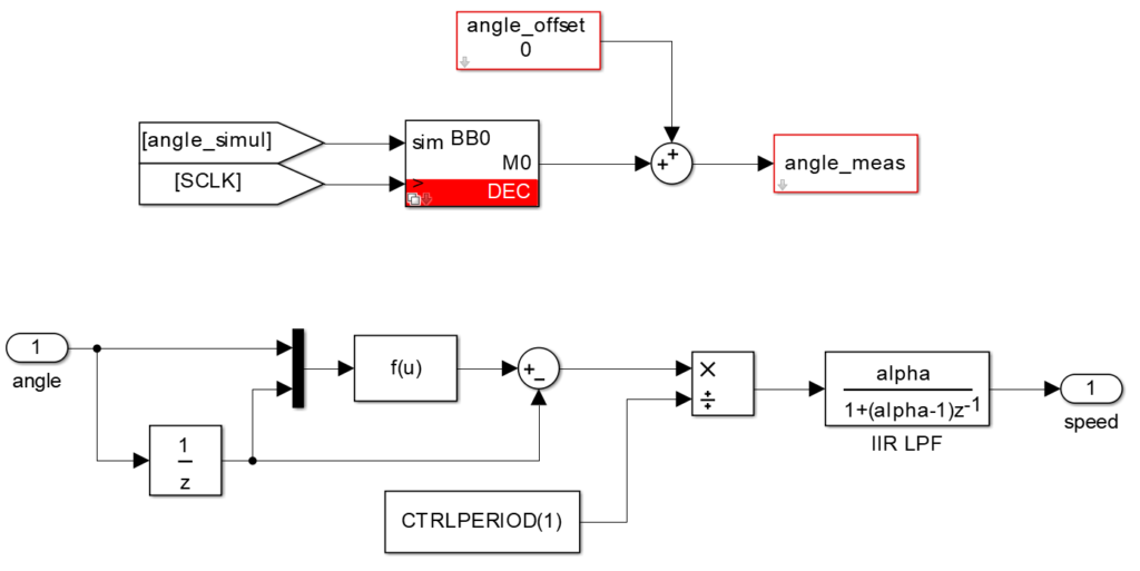
The following function accounts for discontinuities in the measured angle:
f(u) = u(1)+2*pi*((u(1)-u(2))<-pi)-2*pi*((u(1)-u(2)>pi))
PLECS
Similarly to the Simulink implementation, the decoder block (DEC) can be used as follows:
The following function accounts for discontinuities in the measured angle:
f(u) = u(1)+2*pi*((u(1)-u(2))<-pi)-2*pi*((u(1)-u(2)>pi))
C/C++ code
Implementation example
In UserInit: configuration of a differential decoder, with 4096 pulses per rotation and Z signal:
tUserSafe UserInit(void)
{
  // ...

  // Configuration of the decoder (angle measurement)
  Dec_ConfigureInputMode(DECODER_CHANNEL_0, DIFFERENTIAL);
  Dec_ConfigurePulsePerRotation(DECODER_CHANNEL_0, 4096);
  Dec_ConfigureResetMode(DECODER_CHANNEL_0, ZINPUT);

  // ...
}
Code language: C++ (cpp)
In the main interrupt UserInterrupt: get the measured angle and compute the speed. An angle offset can be added to the measured angle to match the angle reference with the application.
tUserSafe UserInterrupt(void)
{
  // ...

  // Get angle from decoder module
  angle_meas = Dec_GetAngle(DECODER_CHANNEL_0) + angle_offset;

  // Speed measurement
  speed_meas_raw = ComputeSpeed(angle_meas, previous_angle);
  previous_angle = angle_meas;
  // Low-pass filter measured speed
  speed_meas = speed_meas - (alpha * (speed_meas - speed_meas_raw));

  // ...
}

float ComputeSpeed(float current_angle, float previous_angle)
{
  float corr = 0.0;

  if (current_angle - previous_angle < -PI)
    corr = 2*PI;
  else if (current_angle - previous_angle > PI)
    corr = -2*PI;

  return (current_angle - previous_angle + corr)/SAMPLING_PERIOD;
}Code language: C++ (cpp)