Table of Contents
This page explains how to get started with the motor drive bundle and the motor testbench. It provides a comprehensive overview of the hardware configuration and step-by-step instructions to commission the equipment.
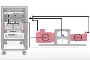
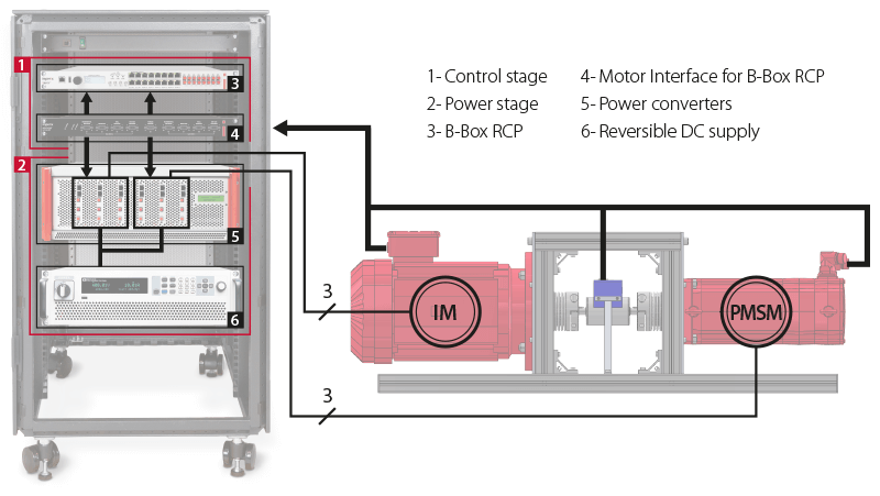
The bundle includes all the necessary equipment to operate the induction machine (IM) and the permanent magnet synchronous machine (PMSM) in a back-to-back configuration. It covers the entire motor-drive system from the digital controller to the power stage and the motors. In this type of setup, one machine can serve as the device under test (DUT), while the other one acts as a programmable mechanical load. The current page covers only the default configuration of the bundle, but a wide range of topologies can be explored thanks to the flexibility of imperix’s solutions. For more details on other possible topologies, please refer to the page How to build a variable speed drive.
Setting up the motor testbench
The default content of the electric motor drive bundle is listed below:
- Programmable controller (B-Box RCP)
- Motor Interface for B-Box RCP
- ACG SDK toolbox for automated generation of the controller code from Simulink or PLECS
- 6x phase-leg modules (PEB8038)
- Motor Testbench, including an induction machine and a permanent magnet synchronous machine (see the datasheet)
- Reversible DC source (third-party)
- All necessary RJ45 and fiber optic cables
- Laboratory safety cables (similar to this one)
Wiring the motor testbench to the power stage
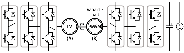
By default, imperix pre-wires the power stage as two inverters with a shared DC bus, as shown in the image below. With this topology, one machine operates as a motor and the other one as a generator. The power circulates in a loop through the DC bus and the shaft, and the DC source compensates for the losses of the system.
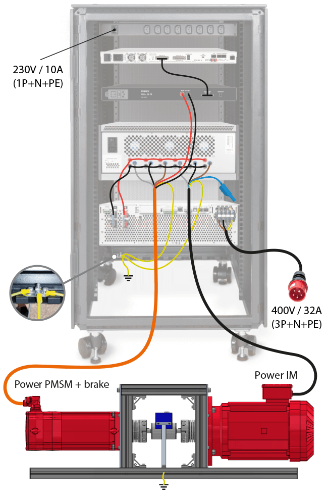
The DC bus is already connected to the DC source out of the box. However, the user must connect the machines to the cabinet themselves, as the motor testbench is shipped on a separate pallet. The image on the right illustrates how to connect the machines to their respective inverter. (Note: the center point of the windings of the IM (blue connector) is left unconnected in the topology considered on this page). Additionally, the built-in brake of the PMSM must be connected to the brake control unit of the motor interface. Make sure to observe the polarity of the brake.
Wiring of the control stage
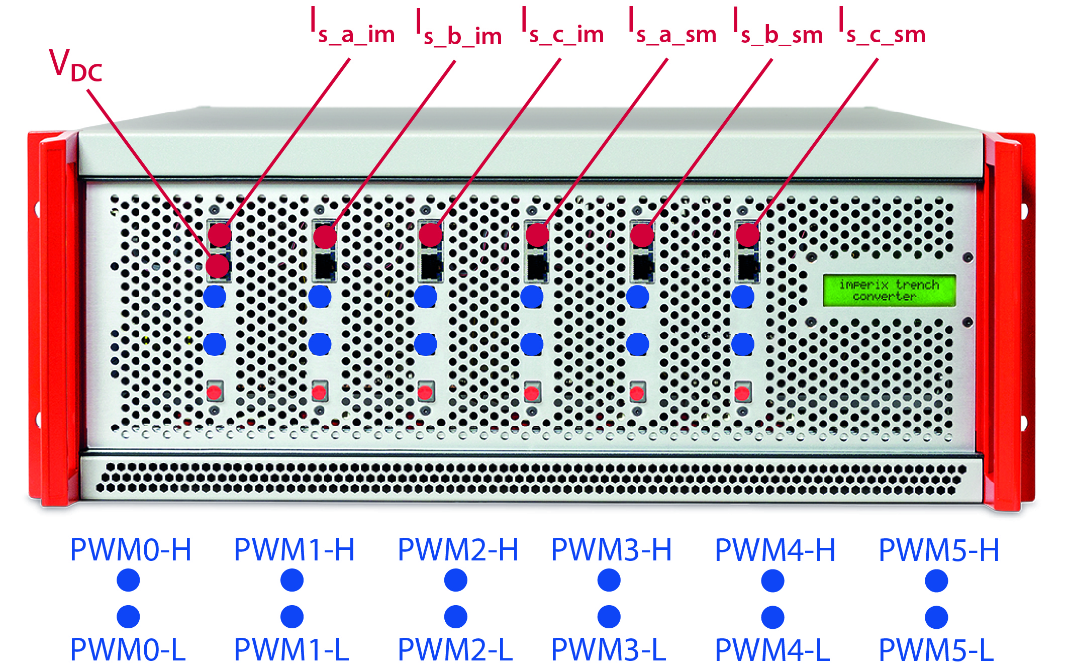
The B-Box controller generates the control signals for the converter (PWM gate signals), based on measured feedbacks (motor currents and DC bus voltage). The gate signals are transmitted to the PEB 8038 modules through optical fibers, whereas the motor currents and the DC bus voltage – measured by the sensors embedded on the PEB 8038 modules – are fed back to the controller through RJ45 cables. The following schematics indicate the assignation of the analog and PWM channels (pre-wired out of the box).
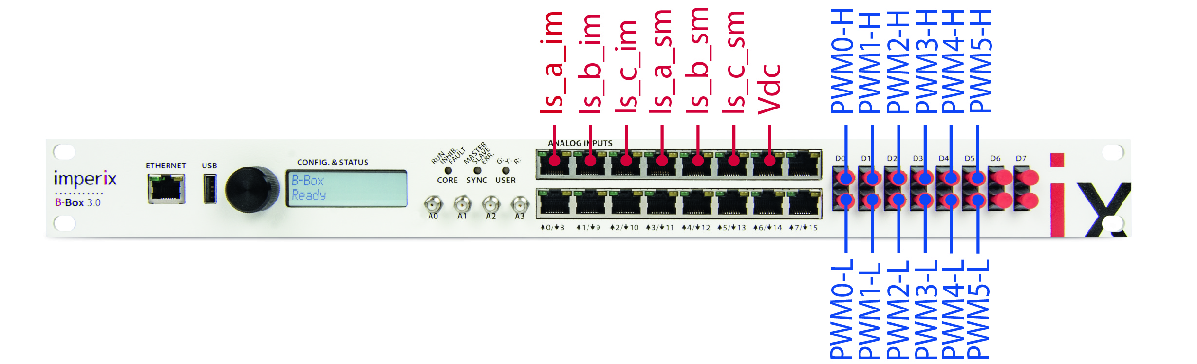
The figure below illustrates how to wire the measurements from the motor testbench to the motor interface box. The green cable of the PMSM, that combines the resolver and temperature measurements, goes in connector X7, and the temperature measurement of the IM (grey cable) goes to the connector X2. Finally, the torque sensor must be connected to X5.
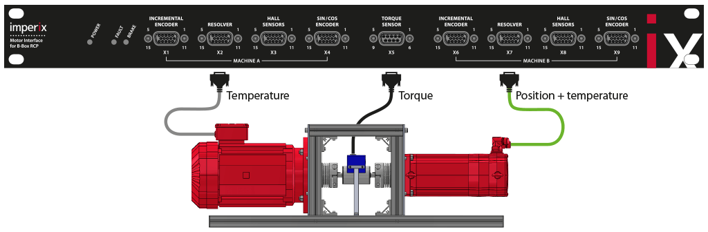
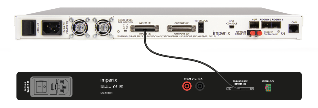
The motor interface is connected to the B-Box through VHDCI Inputs (B) with the provided cable.
Commissioning the motor testbench
The motor testbench is a complex system to drive with multiple converters, control loops, and mechanical elements. Thus, imperix recommends proceeding step-by-step to simplify the commissioning.
Safety considerations
Before starting any experiment, it is essential to take all necessary precautions to operate the system safely. Please observe the safety measures detailed in the panes below.
Test 1: no load test in open-loop
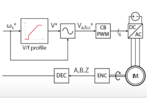
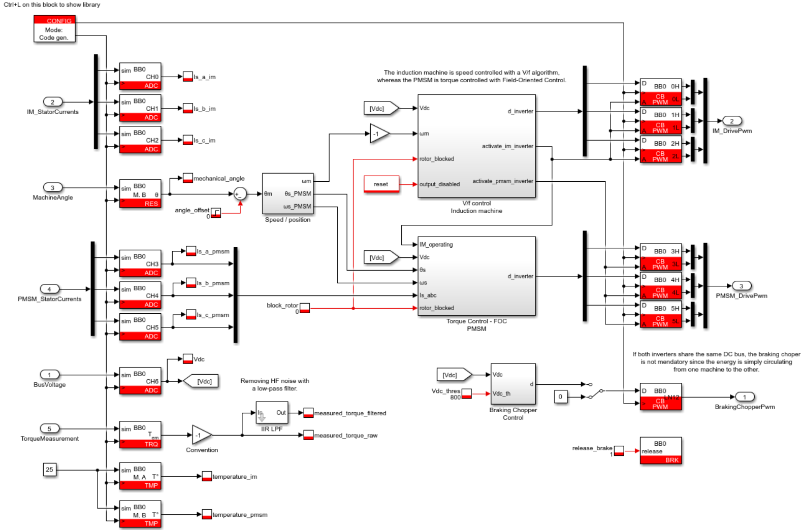
Many control techniques rely on a position sensor to accurately estimate the position of the rotor flux. It is also possible to calculate the angular speed by computing the derivative of the position and using it for closed-loop speed regulation. For this reason, it makes sense to check the correct operation of the resolver first. The Simulink model provided below implements an open-loop V/f control of the IM that sets its speed to a known value without relying on a speed measurement. Additionally, to avoid slowing down the rotor, the PMSM is not supplied (no load test). More details on the control can be found in V/f control of an induction machine.
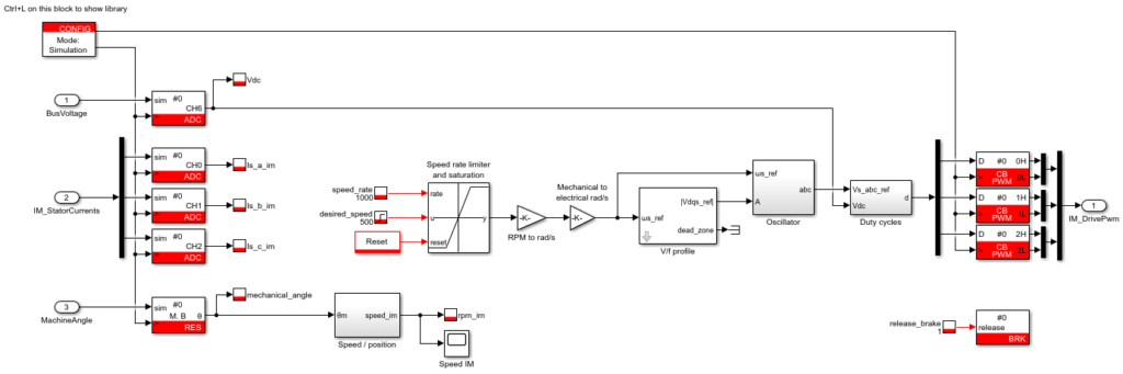
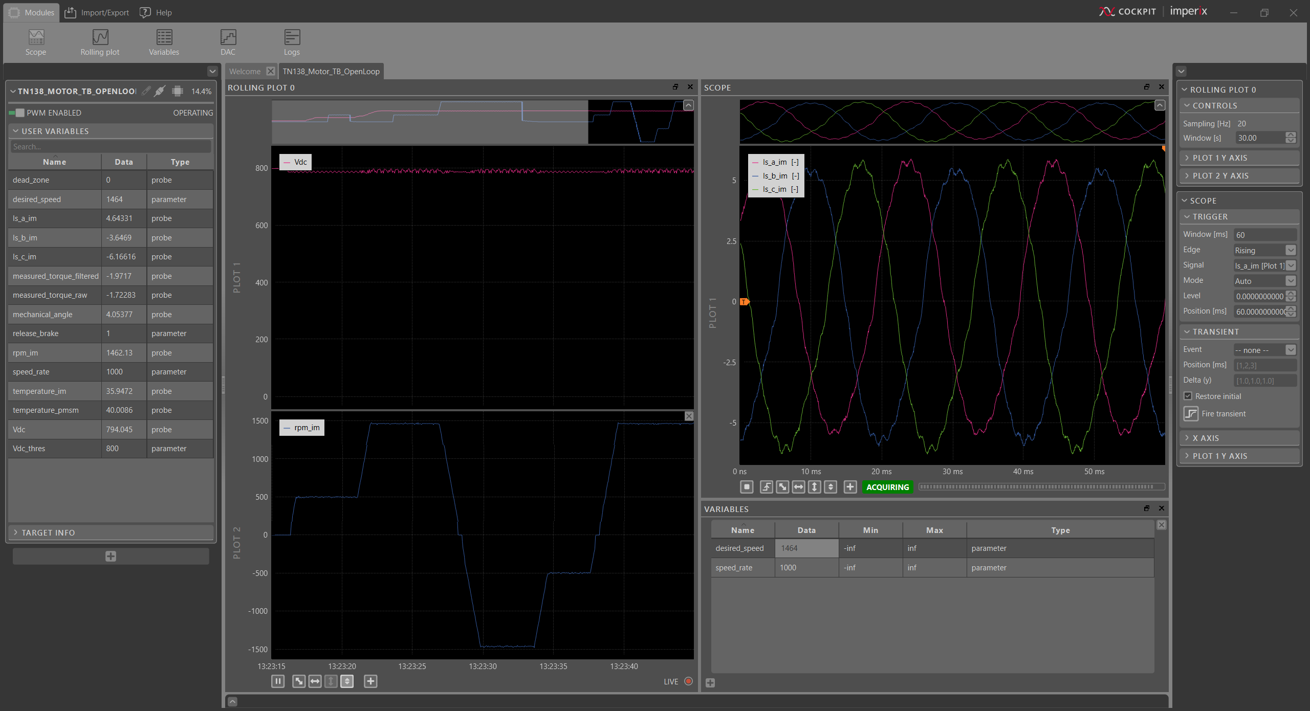
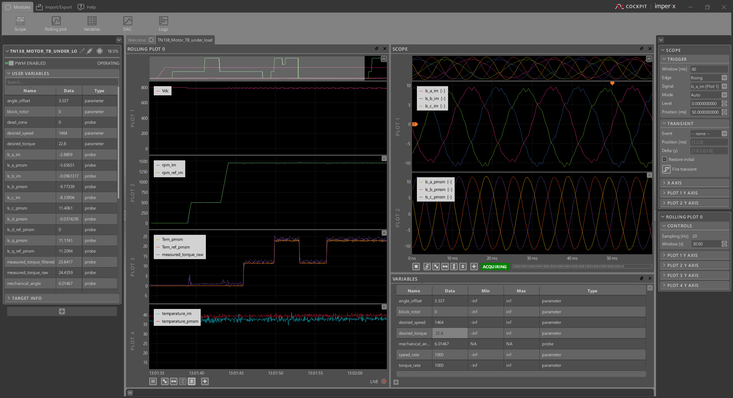
The screenshot below shows how the workspace could look in the end, while running the test procedure.
Test 2: load test
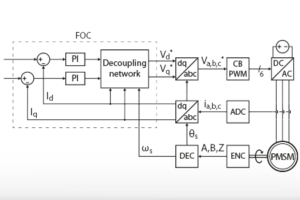
After validating the correct functioning of the resolver, the position measurement can be used by the control. For example, the Simulink model below implements a Field-Oriented Control (FOC) of the PMSM (see TN111 for more details). The goal is to load the IM and operate the motor testbench under nominal conditions. Additionally, the V/f control has been upgraded with a closed-loop speed controller for improved disturbance rejection. Operating the machines under load also gives the opportunity to check the torque and temperature sensors.
The screenshot below shows how the workspace could look in the end, while running the test procedure.
To go further…
… with the motor testbench
The knowledge base presents standard control techniques for both the IM and the PMSM, such as:
- V/f Control of an induction machine (with turn-key code example)
- Rotor Field-Oriented Control of an induction machine (with turn-key code example)
- Field-Oriented Control of a PMSM (with turn-key code example)
- Direct Torque Control of a PMSM
Testing various control techniques is not the only purpose of the motor testbench. It can also serve as a reduced-scale prototype, functionally equivalent to a real-life system. The following articles present two examples of such applications:
… with the motor interface
The motor interface supports different position sensors, allowing the option to replace the motor testbench with another set of machines. The functionalities of the motor interface are available through the ACG and CPP SDKs. Since they are part of the imperix library, they do not require any additional installation procedure.
When using the Simulink or PLECS blocksets, the blocks specific to the Motor Interface are used like any other blocks. They mostly hide the hardware layer and provide only information relevant to the control, such as decoded angle of a machine, temperature measurements in °C, etc. More details can be found in the software documentation: