Table of Contents
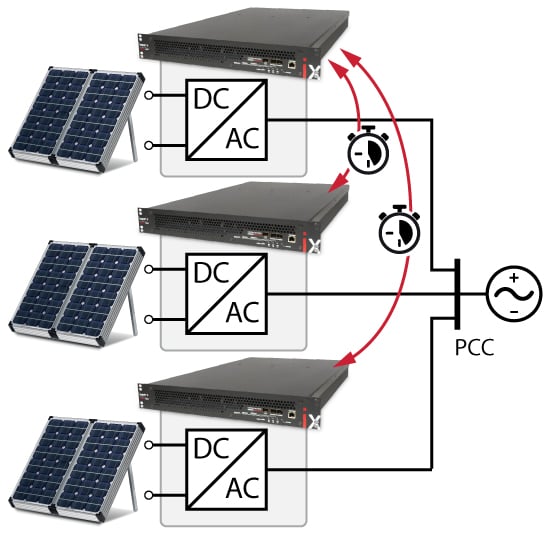
This application showcases a multi-converter system consisting of three DC/AC converters connected to a microgrid, representing a typical scenario such as three photovoltaic inverters sharing a single point of common coupling (PCC).
The focus of this note is on the implementation of the three converters using TPI8032 programmable inverters and their coordinated control with inter-device communication. Furthermore, thanks to the synchronization of modulation signals enabled by imperix’s networked control technology, an interleaved modulation strategy is applied, significantly enhancing harmonic performance at the PCC.
Control implementation of the multi-converter system
Control algorithm
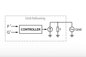
For each converter, the control approach follows that presented in Grid-Following Inverter (TN167) and includes the following features:
- Grid synchronization is achieved using an SRF PLL (TN104).
- The grid-tied inverter employs vector control (TN106) of the grid current.
For simplification purposes, the typical control structure of PV inverters—which includes a boost stage with MPPT control and a DC link voltage control cascaded with grid current control—is entirely bypassed. Instead, only the d- and q-axis currents are controlled. The current references are set as tunable parameters, allowing the user to input values directly. A more comprehensive example of PV inverter control is presented in Three-phase PV inverter for grid-tied applications (AN006).
Controller-to-controller communication
With imperix controllers, various approaches can be used to implement coordinated and/or synchronized control of multi-converter systems. Communication between controllers can be achieved using standard real-time protocols such as CAN or Ethernet, or via Imperix’s proprietary RealSync protocol. The latter is natively supported by all Imperix controllers and offers the advantages of synchronized control execution and modulation without adding implementation complexity. More details on the available options can be found in Real-Time Communication Protocols for B-Box RCP (PN202).
When RealSync is used to exchange user data between controllers running different control codes, this is referred to as master-master communication. This differs from master-slave communication, which occurs transparently between controllers when operating in I/O extension mode. A combination of these approaches is also possible to implement distributed control, known as combined mode in Distributed Control.
Code development in multi-master scenarios
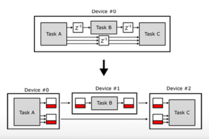
For multi-master operation, each controller should have its own programming model (Simulink or PLECS) and the data exchange between controllers is handled using the SFP block. More details on programming imperix controllers in multi-master setups can be found in Multi-master for distributed networked control (PN158).
In this note, to illustrate controller-to-controller communication, the PCC current reference entered by the user is divided by three in the first converter’s controller and transmitted to the other two converters. Additionally, the activation state of the first controller is shared with the other two, simplifying the operation of the multi-converter system.
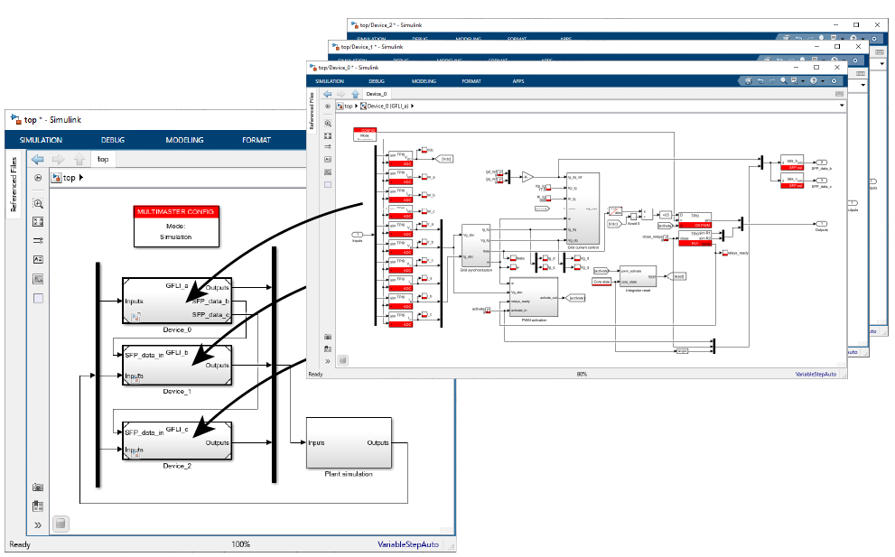
To simplify the testing and development of the three control codes, a top-level Simulink model integrates the three independent models using the template provided in Multi-Master for Distributed Networked Control (PN158). This enables simultaneous code generation for all three models with a single click. Additionally, a plant simulation model is included to facilitate offline testing of the multi-converter system, using simulation models of the Power Library.
Interleaving in multi-converter systems
Similar to the operation of multi-phase DC/DC converters, the operation of several grid-tied inverters can be interleaved. This allows reducing the total current ripple, thereby improving the harmonic performance at the point of common coupling (PCC), notably on the measured voltage.
As presented in [1], the optimal phase-shift angle Ki for each converter depends on the modulation depth. For high modulation indices, such as in grid-tied inverters, the best THD reduction is achieved with:
$$\displaystyle K_i = i\cdot\frac{2\pi}{2n}$$
where \(i\) is the inverter index and n the total number of interleaved converters.
In this case, the phase-shifts are therefore selected as \(K_0=0.0\), \(K_1=\pi/3\), and \(K_2=2\pi/3\), set in the phase parameter of the carrier-based PWM modulator blocks.
References
[1] D. Zhang, F. Wang, R. Burgos, R. Lai and D. Boroyevich, “Impact of Interleaving on AC Passive Components of Paralleled Three-Phase Voltage-Source Converters,” in IEEE Transactions on Industry Applications, vol. 46, May-june 2010.
Practical implementation of the multi-converter system
Control model
The Simulink model used in this note is available for download below. It contains:
GFLI_a.slx,GFLI_b.slx, andGFLI_c.slx: the models containing the control of each convertertop.slx: the top-level model combining the other three modelsGFLI_param.m: a text file defining the system parameters
Minimum requirements:
- ACG SDK 2025.1 or newer, available at imperix.com/downloads/
- MATLAB Simulink R2016a or newer with:
- MATLAB Coder, Simulink Coder, and Embedded Coder
- Simscape Power Systems (offline simulation only)
Test setup
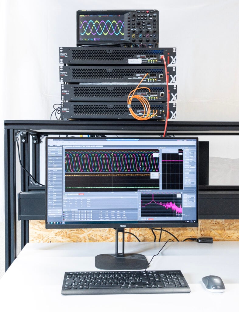
The test setup shown in the picture comprises:
- Three TPI8032 programmable inverters used as grid-tied inverters
- A DC power source to supply the DC sides of the three grid-tied inverters (here, the source is implemented with another TPI8032 controlled separately from the other converters)
- External current probes to measure the PCC currents and display them on an oscilloscope
Experimental results
The test conditions are as follows :
| Parameter | Value |
| AC voltage | 400 V RMS line-to-line |
| DC voltage | 800 V |
| Control and switching frequencies | 50 kHz |
| Converter impedance | 1.05 mH |
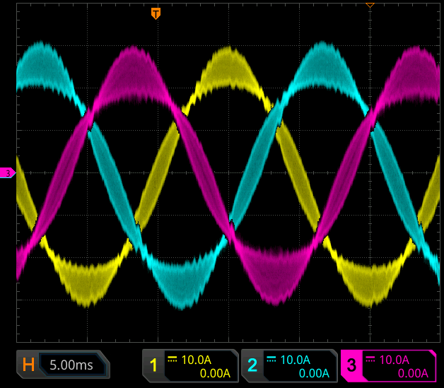
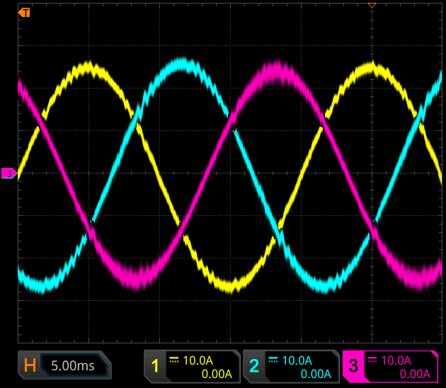
| Grid current reference at PCC | 18 A RMS |
When no interleaving is applied, the current ripple from all three converters adds up, resulting in approximately 10 A peak-to-peak ripple (left scope). With interleaving, this ripple is significantly reduced to around 2 A (right scope).