Table of Contents
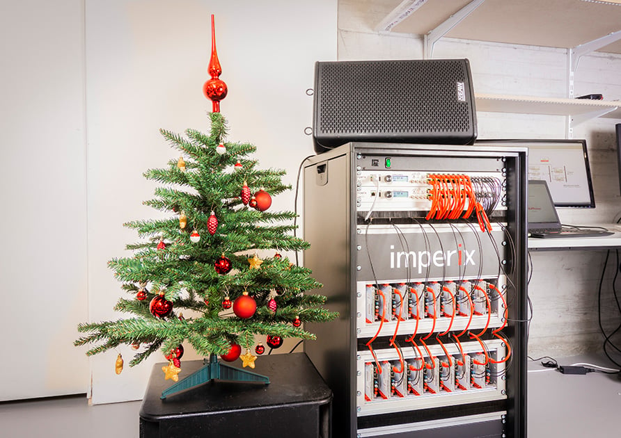
As an informal challenge, we ambitioned to use an existing laboratory-scale Modular Multilevel Converter and build a powerful MMC-based audio amplifier!
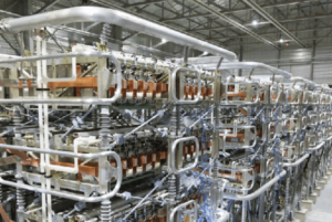
Modular Multilevel Converters (MMC) are best known for their suitability to high-voltage applications, notably large-scale HVDC facilities such as in sub-sea or long-distance energy transport.
In this context, the ability to block high voltages is key. Nevertheless, the high quality of the produced waveforms is also very beneficial to system design, thanks to reduced filtering requirements. Technically, this superior waveform quality is related to two simple yet fundamental benefits:
- The increase of the apparent switching frequency, which is often much higher than the actual switching frequency (typ. in the kHz range, while power semiconductors are actually switching at few tens of Hz).
- The reduced amplitude of the switching harmonics, thanks to a higher number of levels (typ. hundreds of levels/modules).
The technical note DC/AC Modular Multilevel Converter (MMC) (TN153) details an example of a three-phase inverter, using our MMC test bench.
Why use an MMC as an amplifier?
Switching audio amplifiers, often referred to as Class-D amplifiers, share the same need for superior voltage quality. Obviously, entirely different orders of magnitudes of power and frequencies are at stake, but MMCs are theoretically also able to bring attractive benefits for such applications. Therefore, as an informal challenge, we ambitioned to use an existing laboratory-scale MMC as a powerful audio amplifier.
Operation parameters
The following operation parameters were selected. They simultaneously correspond to widely sufficient conditions for an excellent audio experience, as well as non-challenging parameters for our digital controller (B-Box RCP) and our power equipment:
- Sampling is made at 100kHz, which isn’t far from the typical 96kHz of professional audio equipment. That’s anyway much larger than the typical audio spectrum, which covers 20Hz-20kHz.
- Digital control is also made at 100kHz, because there are only a few PI controllers to run (16 in the selected control implementation), so that isn’t a challenge at this frequency.
- Switching frequency is chosen as 25kHz, because once accounting for the phase-shifting (interleaving), the apparent switching frequency becomes 400kHz, which is largely sufficient to push switching harmonics away from the useful spectrum.
- The number of modules per arm is N=4, which is sufficient to benefit from 17 levels on the load, namely the loudspeaker.
These parameters are summarized in the following table:
| Symbol | Parameter | Value |
|---|---|---|
| \(N\) | Number of submodules per arm | 4 |
| \(f_{sw}\) | Actual switching frequency | 25 kHz |
| \(f_{sw,a}\) | Apparent switching frequency (\(f_{sw,a}=16\cdot f_{sw}\)) | 400 kHz |
| \(f_s=f_{ctrl}\) | Sampling and control frequency | 100 kHz |
| \(n_a\) | Apparent number of levels (\(n_a=4N+1\)) | 17 |
Downloads
Control overview
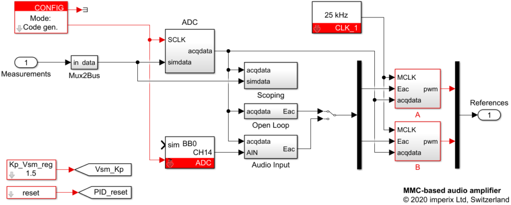
The control of the Modular Multilevel Converter has been implemented in the simplest possible way. The requested converter voltage \(E_{AC}\) can be generated in a purely open-loop fashion, either using:
- A basic sinusoidal waveform generator, used for debug purposes (see block Open Loop).
- A signal input (see block Audio Input), which directly reads an analog input of the B-Box and to which a simple custom-made 3.5mm jack cable is connected.
Submodules balancing
The generally delicate balancing of the converter submodules is here achieved using phase-shifted carrier-based modulators, whose duty cycles are slightly altered for balancing purposes.
This technical approach, first proposed for MMC in [1], has proven since to be simple and effective. It consists in adding or subtracting a small amount of voltage to each submodule reference EMF, depending on the current sign.
However, as the reference voltage for each local control loop is here set to be the average capacitor voltage within one arm, it guarantees the balancing inside each arm, but not in-between the arms. This second stage of balancing is here addressed indirectly, using the fact that the duty-cycle \(m\) is computed by dividing the resulting reference EMF by \(V_{SM,ref}\) instead of the actual measurement (\(V_{SM,ref}\) is a constant setpoint, set for all submodules inside all arms).
This simple technique is interesting as it was proven to be asymptotically stable [2]. However, it fails at properly rejecting the capacitor voltage fluctuations, which may impede the overall harmonic performance. As such, we would not recommend it for more serious use of an MMC in such an application.
An alternative approach, using sort-&-select balancing and modulation would be possible. Some hints about the functioning of the pre-implemented modulators are given in TN160.

Modulation and interleaving
Having \(N=4\) modules per arm, the carrier-based modulators are phase-shifted as follows:
- \(\phi_{modules} = \frac{2\pi}{4}\) in-between modules of the same arm. The resulting arm-level EMF therefore possesses N+1 levels, with an apparent switching frequency of \(f_{sw,a}=4\cdot f_{sw}\).
- \(\phi_{arms} = \frac{2\pi}{8}\) in-between arms of the same phase-leg. The resulting arm-level EMF (e.g. \(E_A\) or \(E_B\)) therefore possesses \(2N+1\) levels, with an apparent switching frequency of \(f_{sw,a}=8\cdot f_{sw}\).
- \(\phi_{legs} = \frac{2\pi}{16}\) in-between phase-leg. The resulting converter-level EMF (\(E_L\)) therefore possesses \(4N+1\) levels, with an apparent switching frequency of \(f_{sw,a}=16\cdot f_{sw}\).
These waveforms can be analyzed from the following simulation results:

Experimental results
Experimental results are reported below. They correspond to measurements made for a pure sine wave at 1kHz.
First, the voltage waveform at no load is presented. The various levels can be identified, although the imperfect balancing prevents from clearly identifying all levels distinctively. The provided Fourier transform also shows that switching harmonics are still present at 100kHz and 300kHz, at levels that are still higher than the 400kHz ones.

Second, the current waveform is presented when the loudspeaker is physically connected, corresponding to more reasonable operating conditions. In this case, switching harmonics become naturally filtered by the low-pass behavior of the loudspeaker itself (resonant circuit) and imperfections of the sine wave become barely visible. Nevertheless, harmonic distorsion is still present (about 1%), mostly constituted by third-order harmonics).

Short presentation video
Academic references
[1] M. Hagiwara and H. Akagi, “PWM Control and Experiment of Modular Multilevel
Converters,” in Proc. PESC Conference, Rhodes, Greece, 2008. https://doi.org/10.1109/PESC.2008.4591917
[2] L. Harnefors, S. Norrga, A. Antonopoulos and H.-P. Nee, “Dynamic
modeling of modular multilevel converters,” in Proc. EPE Conference, Birmingham,
Sept. 2011. https://ieeexplore.ieee.org/document/6020628


